Parameter:
1>. Work Voltage:DC 12V-30V; (> 100MA)
2>. PWM Receiver Frequency:1KHZ-3KHZ
3>. PWM signal input level range:
The peak of 4.5V to 10V level. The short cap install in ‘5V’. This level is used for normal controller or 5V MCU
The peak of 12V to 24V level, so inserted in 24V. The short cap install in ‘24V’. This level is used for normal PLC controller
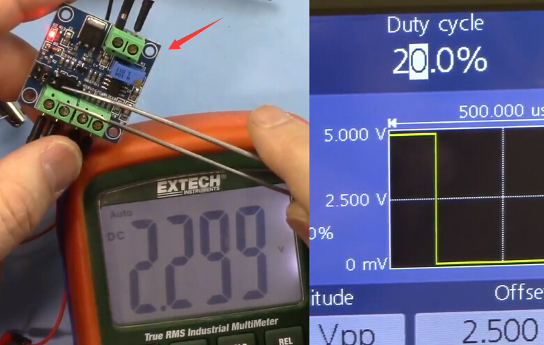
4>. Conversion range:0%-100% PWM to 0-10V
5>. Allowable error:5%
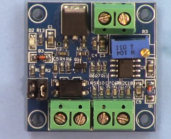
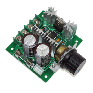
Hardware Interface:
| VCC | DC 12V-30V |
| GND | Ground |
| PWM | Positive of PWM input signal |
| GND | Negative of input signal |
| VOUT | Output Voltage 0-10V |
| GND | Output Voltage Ground |
Operation instructions:
After power on, without input signal, the output is 0V, so only input can output.
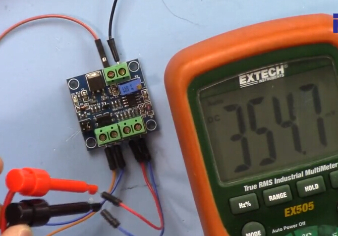
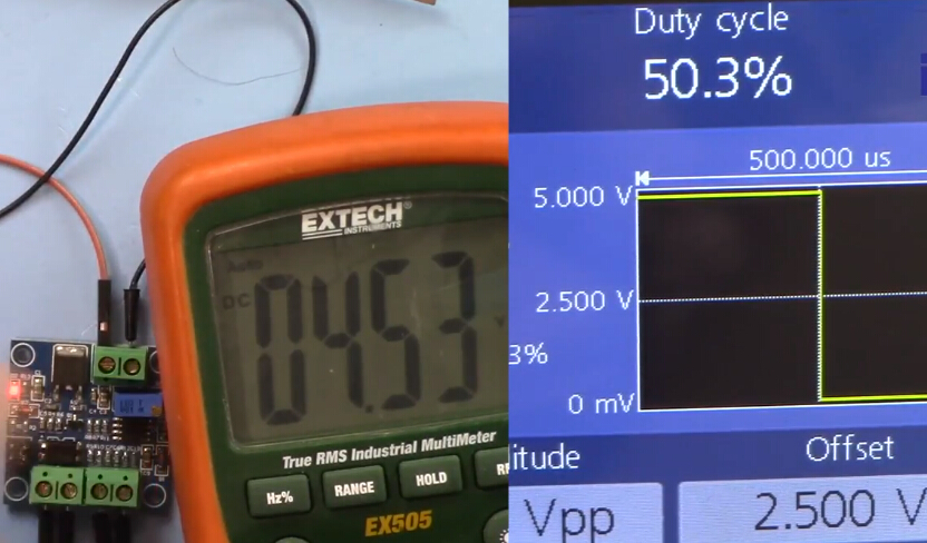
The first time when the power is on, it is best to do a calibration debugging: Input a 50% duty ratio signal to PWM/GND and adjust the relative amplitude short cap.
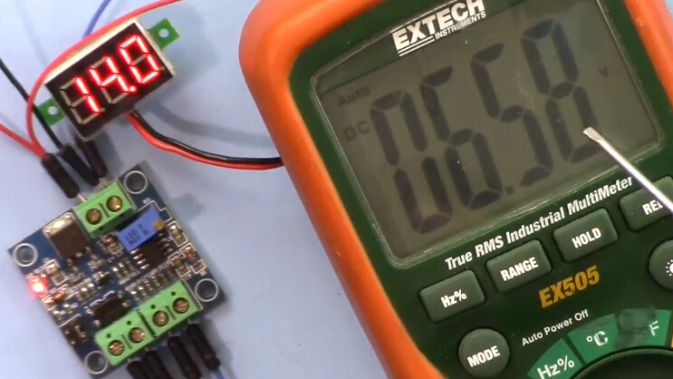
The frequency is 1KHZ-3KHZ, Measured VOUT and GND with a multimeter and it will display 5V.
Adjust potentiometer to make sure display 5.00V on multimeter. This will calibrate your pulse signal to this module.
When the frequency changes, the correspondences may be offset and need to be re calibrated.
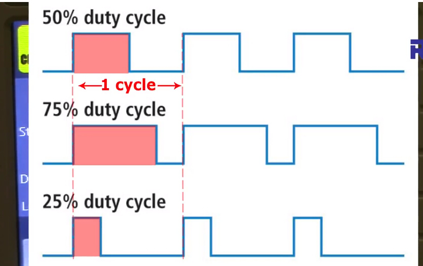
The output voltage can be adjusted by adjusting the duty ratio.
The accuracy can be controlled by adjusting the potentiometer.
Tested by ICStation’s Outstanding Partner Robojax: