![]()
This short article will show you how to transform your Arduino into a cell phone. Remember that you can always visit us or contact us during our normal opening hours.
How to connect SIM900
This model does not include the pins to mount it directly on the Arduino and since this card is controlled by UART, we only need TX and RX pins. Below is how to connect SIM900 to Arduino UNO:
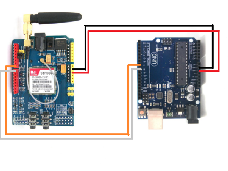
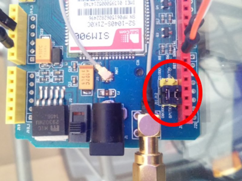
Because we’re using the pins 7 and 8 for the data transmission between SIM900 and Arduino, make sure that the jumpers of the GSM card are positioned in D7 and D8 to activate these pins.
Below is a code that will let you make a call, hang up, and then send a text message to a mobile phone:
/ *
Professional Technological Tools
www.hetpro-store.com
Original Tutorial:
https://tronixstuff.com/2014/01/08/tutorial-arduino-and-sim900-gsm-modules/
AT commands:
https://probots.co.in/Manuals/SIM900%20GSM%20Modem%20-%20Starter%20Guide.pdf
Data sheet:
Instructions for Arduino: Set the serial terminal to 19200 baud so you can see the messages.
* /
# include < SoftwareSerial.h > ;
SoftwareSerial SIM900 ( 7 , 8 ); // Configure the serial port for the GSM SIM
char incoming_char = 0 ; // Variable that stores the characters sent by the GSM SIM
int exit = 0 ;
void setup ()
{
SIM900. begin ( 19200 ); // Set up serial speed for the SIM
delay ( 25000 ); // Delay to find a RED
Serial. begin ( 19200 ); // Set serial speed for the Arduino
Serial. println ( ” OK ” ); // Message OK in the arduino, to know that everything is fine.
}
void call ()
// Function that allows to call a local cell
{
SIM900. println ( ” ATD 33XXXXXXXX; ” ); // Cellular
delay ( 100 );
SIM900. println ();
delay ( 30000 ); // wait for 30 seconds …
SIM900. println ( ” ATH ” ); // Drop the phone
delay ( 1000 );
}
void message_sms ()
// Function to send text message
{
SIM900. print ( ” AT + CMGF = 1 \ r ” ); // AT command to send SMS message
delay ( 100 );
SIM900. println ( ” AT + CMGS = \” 33XXXXXXXX \ ” ” ); // recipient’s mobile number, in international format
delay ( 100 );
SIM900. println ( ” Greetings from HetPro ” ); // message to send
delay ( 100 );
SIM900. println (( char ) 26 ); // End AT command with a ^ Z, ASCII code 26 // End command
delay ( 100 );
SIM900. println ();
delay ( 5000 ); // Time for the message to be sent
Serial. println ( ” SMS sent successfully ” );
}
void wait_message ()
{
exit = 1 ;
while (exit == 1 )
{
if (SIM900. available ()> 0 )
{
incoming_char = SIM900. read (); // Get the character from the serial serial port.
Serial. print (incoming_char); // Print the incoming character to the terminal.
exit = 0 ;
}
}
}
void mode_receives_message ()
{
// Set text mode to send or receive messages
SIM900. print ( ” AT + CMGF = 1 \ r ” ); // set SMS mode to text
delay ( 100 );
SIM900. print ( ” AT + CNMI = 2,2,0,0,0 \ r ” );
// blurt out contents of new SMS upon receipt to the GSM shield’s serial out
delay ( 1000 );
}
void loop ()
{
call (); // Flame
message_sms (); // Send message
mode_receives_message ();
for (;;)
{
if (SIM900. available ()> 0 )
{
incoming_char = SIM900. read (); // Get the character from the serial serial port.
Serial. print (incoming_char); // Print the incoming character to the terminal.
}
if (Serial. available ()> 0 )
{
if (Serial. read () == ‘ A ‘ ) break ;
}
}
Serial. println ( ” OK-2 ” );
delay ( 100 );
SIM900. println ();
delay ( 30000 );
while ( 1 ); // Wait for an indefinite period
}
Once you upload the code on your Arduino, turn on the SIM module with the PowerKey button and wait for the Netlight to flash once every 2 seconds. (Picture Below for reference)
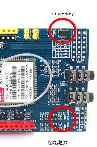
Open the serial port, and check the messages you get every 30 seconds…Once you upload the code on your Arduino, turn on the SIM module with the PowerKey button and wait for the Netlight to flash once every 2 seconds. (Picture Below for reference)
You can also try the AT Commands, to configure this same module…
Source: https://hetpro-store.com/TUTORIALES/sim900-gsm-shieldarduino/

