Description
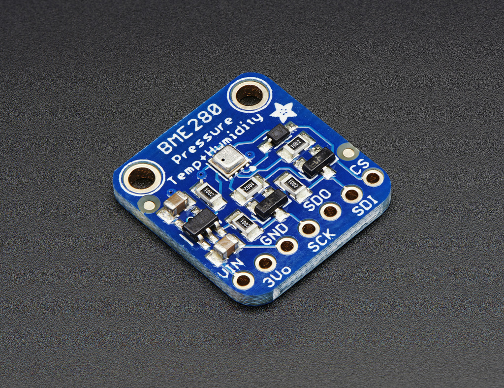
Nice sensor right? So they made it easy for you to get right into your next project. The surface-mount sensor is soldered onto a PCB and comes with a 3.3V regulator and level shifting so you can use it with a 3V or 5V logic microcontroller without worry.
Power Pins:
Vin – this is the power pin. Since the sensor chip uses 3 VDC, we have included a voltage regulator on board that will take 3-5VDC and safely convert it down. To power the board, give it the same power as the logic level of your microcontroller – e.g. for a 5V micro like Arduino, use 5V
3Vo – this is the 3.3V output from the voltage regulator, you can grab up to 100mA from this if you like
GND – common ground for power and logic
SPI Logic pins:
All pins going into the breakout have level shifting circuitry to make them 3-5V logic level safe. Use whatever logic level is on Vin!
- SCK – This is the SPI Clock pin, its an input to the chip
- SDO – this is the Serial Data Out / Master In Slave Out pin, for data sent from the BMP183 to your processor
- SDI – this is the Serial Data In / Master Out Slave In pin, for data sent from your processor to the BME280
- CS – this is the Chip Select pin, drop it low to start an SPI transaction. Its an input to the chip
If you want to connect multiple BME280’s to one microcontroller, have them share the SDI, SDO and SCK pins. Then assign each one a unique CS pin.
I2C Logic pins:
- SCK – this is also the I2C clock pin, connect to your microcontrollers I2C clock line.
- SDI – this is also the I2C data pin, connect to your microcontrollers I2C data line.