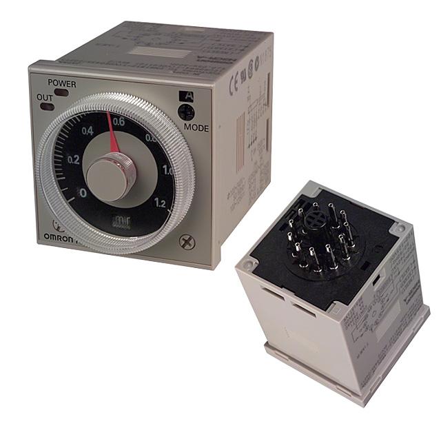
Description
11-pin Models
| Output | Supply voltage | Input type | Time range | Operating mode *2 | Model *1 |
|---|---|---|---|---|---|
| Contact | 100 to 240 VAC (50/60 Hz)/ 100 to 125 VDC |
No-voltage input |
0.05 s to 300 h | Eight multi-modes: A, B, B2, C, D, E, G, J |
H3CR-A |
| 24 to 48 VAC (50/60 Hz)/ 12 to 48 VDC |
|||||
| 100 to 240 VAC (50/60 Hz)/ 100 to 125 VDC |
Voltage input | Eight multi-modes: A, B, B2, C, D, E, G, J |
H3CR-AP | ||
| 24 to 48 VAC (50/60 Hz)/ 12 to 48 VDC |
|||||
| 100 to 240 VAC (50/60 Hz)/ 100 to 125 VDC |
No-voltage input |
0.1 s to 600 h | H3CR-A-301 | ||
| 24 to 48 VAC (50/60 Hz)/ 12 to 48 VDC |
|||||
| Transistor (Photocoupler) |
24 to 48 VAC (50/60 Hz)/ 12 to 48 VDC |
0.05 s to 300 h | H3CR-AS |
8-pin Models
| Output | Supply voltage | Input type | Time range | Operating mode *2 | Model *1 |
|---|---|---|---|---|---|
| Contact | 100 to 240 VAC (50/60 Hz)/ 100 to 125 VDC |
No-input available |
0.05 s to 300 h | Five multi-modes: A, B, B2, E, J (Power supply start) |
H3CR-A8 |
| 24 to 48 VAC (50/60 Hz)/ 12 to 48 VDC |
|||||
| 100 to 240 VAC (50/60 Hz)/ 100 to 125 VDC |
0.1 s to 600 h | H3CR-A8-301 | |||
| 24 to 48 VAC (50/60 Hz)/ 12 to 48 VDC |
|||||
| Transistor (Photocoupler) |
24 to 48 VAC (50/60 Hz)/ 12 to 48 VDC |
0.05 s to 300 h | H3CR-A8S | ||
| Time-limit contact and instantaneous contact |
100 to 240 VAC (50/60 Hz)/ 100 to 125 VDC |
H3CR-A8E | |||
| 24 to 48 VAC/VDC (50/60 Hz) |
Accessories (Order Separately)
Adapter, Protective Cover, Hold down Clip, Setting Ring and Panel Cover
| Name/specifications | Models | |
|---|---|---|
| Flush Mounting Adapter | Y92F-30 | |
| Y92F-73 *1 | ||
| Y92F-74 *1 | ||
| Y92F-38 | ||
| Protective Cover | Y92A-48B *2 | |
| Hold-down Clip (Sold in sets of two) | For PF085A Socket | Y92H-8 |
| For PL08 or PL11 Sockets | Y92H-7 | |
| Setting Ring A | Y92S-27 *3 | |
| Setting Ring B and C | Y92S-28 *3 | |
| Panel Cover | Light gray (5Y7/1) | Y92P-48GL *4 |
| Black (N1.5) | Y92P-48GB *4 | |
-74 Flush Mounting Adapter.
*2. The Y92A-48B Protective Cover is made from hard plastic. Remove the Protective Cover to change to set value. The
Y92F-73/-74 Flush Mounting Adapter and the Y92P-48G[] Panel Cover cannot be used at the same time with Y92A-
48B Protective Cover.
*3. The Y92S-27/-28 Setting Ring cannot be used alone. It must be used together with the Y92P-48G[] Panel Cover.
*4. The Y92A-48B Protective Cover and the Y92F-73/-74 Flush Mounting Adapter cannot be used at the same time with the
Y92P-48G[] Panel Cover.
Sockets
| Timer | Round Sockets | ||
|---|---|---|---|
| Pin | Connection | Terminal | Models |
| 11-pin | Front Connecting | DIN track mounting | P2CF-11 |
| DIN track mounting (Finger-safe type) | P2CF-11-E | ||
| Back Connecting | Screw terminal | P3GA-11 | |
| Solder terminal | PL11 | ||
| Wrapping terminal | PL11-Q | ||
| PCB terminal | PLE11-0 | ||
| 8-pin | Front Connecting | DIN track mounting | P2CF-08 |
| DIN track mounting (Finger-safe type) | P2CF-08-E | ||
| DIN track mounting | PF085A | ||
| Back Connecting | Screw terminal | P3G-08 | |
| Solder terminal | PL08 | ||
| Wrapping terminal | PL08-Q | ||
| PCB terminal | PLE08-0 | ||
terminals.
2. The P3GA-11 and P3G-08 Socket can be used together with the Y92A-48G Terminal Cover to implement finger
protection.
3. For details, refer to your OMRON website.
Terminal Cover
| Application | Model | Remarks |
|---|---|---|
| For back connecting socket | Y92A-48G | For P3G-08 and P3GA-11 |
| Item | H3CR-A/-AS/-A-301 | H3CR-AP | H3CR-A8/-A8S/-A8-301 | H3CR-A8E |
|---|---|---|---|---|
| Operating mode | A: ON-delay B: Flicker OFF start B2: Flicker ON start C: Signal ON/OFF-delay D: Signal OFF-delay E: Interval G: Signal ON/OFF-delay J: One-shot |
A: ON-delay (power supply start) B: Flicker OFF start (power supply start) B2: Flicker ON start (power supply start) E: Interval (power supply start) J: One-shot (power supply start) |
||
| Pin type | 11-pin | 8-pin | ||
| Input type | No-voltage input | Voltage input | — | |
| Time-limit output type | H3CR-A/-A8/-AP/-A-301/-A8-301: Relay output (DPDT) H3CR-AS/-A8S: Transistor output (NPN/PNP universal) *1 |
Relay output (SPDT) |
||
| Instantaneous output type | — | Relay output (SPDT) |
||
| Mounting method | DIN track mounting, surface mounting, and flush mounting | |||
| Approved standards | UL508, CSA C22.2 No.14, NK, Lloyds, CCC: GB/T 14048.5 *2 Conforms to EN61812-1 and IEC60664-1 (VDE0110) 4kV/2. Output category according to EN60947-5-1 for Timers with Contact Outputs. Output category according to EN60947-5-2 for Timers with Transistor Outputs. |
|||
For details, refer to your OMRON website.
*2 CCC certification requirements
| Recommended fuse | Contact Output: 0216005 (250 VAC, 5 A), manufactured by Littelfuse Transistor Output: 0216.100 (250 VAC, 100 mA) manufactured by Littelfuse |
|---|---|
| Rated operating voltage Ue Rated operating current Ie |
Contact Output: AC-15: Ue: 250 VAC, Ie: 3 A AC-13: Ue: 250 VAC, Ie: 5 A DC-13: Ue: 30 VDC, Ie: 0.5 A Transistor Output: DC-13: Ue: 30 VDC, Ie: 0.1 A |
| Rated insulation voltage | 250 V |
| Rated impulse withstand voltage (altitude: 2,000 m max.) |
4 kV (at 240 VAC) |
| Conditional short-circuit current | 1000 A |
Time Ranges
operate instantaneously at all time range settings.
For details, refer to your OMRON website.
Standard (0.05-s to 300-h) Models
| Time unit | s (sec) | ×10 s (10 sec) | min (min) | ×10 min (10 min) | h (hrs) | ×10 h (10 hrs) | |
|---|---|---|---|---|---|---|---|
| Full scale setting |
1.2 | 0.05 to 1.2 | 1.2 to 12 | 0.12 to 1.2 | 1.2 to 12 | 0.12 to 1.2 | 1.2 to 12 |
| 3 | 0.3 to 3 | 3 to 30 | 0.3 to 3 | 3 to 30 | 0.3 to 3 | 3 to 30 | |
| 12 | 1.2 to 12 | 12 to 120 | 1.2 to 12 | 12 to 120 | 1.2 to 12 | 12 to 120 | |
| 30 | 3 to 30 | 30 to 300 | 3 to 30 | 30 to 300 | 3 to 30 | 30 to 300 | |
Ratings
| Rated supply voltage *1 *2 *5 |
100 to 240 VAC (50/60 Hz)/100 to 125 VDC, 24 to 48 VAC (50/60 Hz)/12 to 48 VDC (24 to 48 VAC/VDC for H3CR-A8E) *3 |
|---|---|
| Operating voltage range | 85% to 110% of rated voltage (90% to 110% at 12 to 48 VDC) |
| Power reset | Minimum power-opening time: 0.1 s |
| Input *6 | No-voltage Input ON impedance: 1 kΩ max. ON residual voltage: 1 V max. OFF impedance: 100 kΩ min. Voltage Input Max. permissible capacitance between inputs lines (terminals 6 and 7): 1,200 pF Load connectable in parallel with inputs (terminals 6 and 7). 100 to 240 VAC/100 to 125 VDC High (logic) level: 85 to 264 VAC/85 to 137.5 VDC Low (logic) level: 0 to 10 VAC/0 to 10 VDC 24 to 48 VAC/12 to 48 VDC High (logic) level: 20.4 to 52.8 VAC/10.8 to 52.8 VDC Low (logic) level: 0 to 2.4 VAC/0 to 1.2 VDC |
| Power consumption | H3CR-A/-A8 100 to 240 VAC/100 to 125 VDC (When at 240 VAC, 60 Hz) Relay ON: approx. 2.0 VA (1.6 W), Relay OFF: approx. 1.3 VA (1.1 W) 24 to 48 VAC/12 to 48 VDC (When at 24 VDC) Relay ON: approx. 0.8 W, Relay OFF: approx. 0.2 W H3CR-AP *3 100 to 240 VAC/100 to 125 VDC (When at 240 VAC, 60 Hz) Relay ON: approx. 2.5 VA (2.2 W) *4, Relay OFF: approx. 1.8 VA (1.7 W) *4 24 to 48 VAC/12 to 48 VDC (When at 24 VDC) Relay ON: approx. 0.9 W *4, Relay OFF: approx. 0.3 W *4 H3CR-A8E 100 to 240 VAC/100 to 125 VDC (When at 240 VAC, 60 Hz) Relay ON/OFF: approx. 2 VA (0.9 W) 24 to 48 VAC/VDC (When at 24 VDC) Relay ON/OFF: approx. 0.9 W H3CR-AS/-A8S 24 to 48 VAC/12 to 48 VDC (When at 24 VDC) Output ON: 0.3 W, Output OFF: 0.2 W |
| Control outputs | Models with Contact Outputs H3CR-A/-A8/-AP 5A at 250 VAC/30 VDC, 0.15A at 125 VDC, resistive load (cosφ = 1) Minimum applied load: 10mA at 5 VDC (failure level: P reference value) Contact materials: Ag-alloy H3CR-A8E 5A at 250 VAC/30 VDC, 0.15A at 125 VDC, resistive load (cosφ = 1) Minimum applied load: 10mA at 5 VDC (failure level: P reference value) Contact materials: AgSnIn Transistor output: Open collector(NPN/PNP) H3CR-AS/-A8S 100 mA max at 30 VDC max., residual voltage: 2 VDC max. |
*2. Do not use an inverter output as the power supply. Refer to your OMRON website for details.
*3. Models with 24-to-48-VAC or 12-to-48-VDC power supply have inrush current. Caution is thus required when turning
ON and OFF power to the Timer with a non-contact output from a device such as a sensor. (Models with an inrush
current of approximately 50 mA and a 24-VDC power supply are available (the H3CR-A-302 and H3CR-A8-302).)
For details, consult your OMRON sales representative.
*4. The values are for when the terminals 2 and 7 and terminals 10 and 6 are short-circuited, and include the
consumption current of the input circuit.
*5. Refer to your OMRON website when using the Timer together with a 2-wire AC proximity sensor.
*6. For details, see Input Connections: No-voltage Input Signal Levels on Catalog, and Input Connections: Voltage Input
Signal Levels on Catalog.
Characteristics
| Accuracy of operating time |
±0.2% FS max. (±0.2%±10 ms max. in a range of 1.2 s or 3 s) |
|---|---|
| Setting error | ±5% FS ±50 ms *1 |
| Reset time | Min. power-opening time: 0.1 s max. Min. pulse width: 0.05 s (H3CR-A/-AS) |
| Reset voltage | 10% max. of rated supply voltage |
| Influence of voltage *2 | ±0.2% FS max. (±0.2%±10 ms max. in a range of 1.2 s or 3 s) |
| Influence of temperature | ±1% FS max. (±1%±10 ms max. in a range of 1.2 s or 3 s) |
| Insulation resistance | 100 MΩ min. (at 500 VDC) |
| Dielectric strength | 2,000 VAC (1,000 VAC for H3CR-A[]S), 50/60 Hz for 1 min (between current-carrying metal parts and exposed non-current-carrying metal parts) 2,000 VAC (1,000 VAC for H3CR-A[]S), 50/60 Hz for 1 min (between control output terminals and operating circuit) 2,000 VAC, 50/60 Hz for 1 min (between contacts of different polarities) 1,000 VAC, 50/60 Hz for 1 min (between contacts not located next to each other) 2,000 VAC, 50/60 Hz for 1 min (between input and control output terminals and operation circuit) for H3CR-AP |
| Impulse withstand voltage |
5 kV (between power terminals) for 100 to 240 VAC/100 to 125 VDC, 1 kV for 24 to 48 VAC/12 to 48 VDC 5 kV (between current-carrying terminal and exposed non-current-carrying metal parts) for 100 to 240 VAC/100 to 125 VDC, 1.5 kV for 24 to 48 VAC/12 to 48 VDC and 24 to 48 VAC/VDC |
| Noise immunity | ±1.5 kV (between power terminals) and ±600 V (between no-voltage input terminals), square-wave noise by noise simulator (pulse width: 100 ns/1 μs, 1-ns rise) |
| Static immunity | Malfunction: 8 kV Destruction: 15 kV |
| Vibration resistance | Destruction: 10 to 55 Hz with 0.75-mm single amplitude each in 3 directions for 2 hours each Malfunction: 10 to 55 Hz with 0.5-mm single amplitude each in 3 directions for 10 minutes each |
| Shock resistance | Destruction: 1,000 m/s2 3 times each in 6 directions Malfunction: 100 m/s2 3 times each in 6 directions |
| Ambient temperature | Operating: -10°C to 55°C (with no icing) Storage: -25°C to 65°C (with no icing) |
| Ambient humidity | Operating: 35% to 85% |
| Life expectancy *4 | Mechanical: 20,000,000 operations min. (under no load at 1,800 operations/h) Electrical: 100,000 operations min. (5 A at 250 VAC, resistive load at 1,800 operations/h) *3 |
| EMC | (EMI) EN61812-1 Emission Enclosure: EN55011 Group 1 class A Emission AC Mains: EN55011 Group 1 class A (EMS) EN61812-1 Immunity ESD: IEC61000-4-2 Immunity RF-interference: IEC61000-4-3 Immunity Burst: IEC61000-4-4 Immunity Surge: IEC61000-4-5 Immunity Conducted Disturbance: IEC61000-4-6 Immunity Voltage Dip/Interruption: IEC61000-4-11 |
| Case color | Light gray (Munsell 5Y7/1) |
| Degree of protection | IP40 (panel surface) |
| Weight | Approx. 90 g |
*1. The value is ±5% FS +100 ms to −0 ms max. when the C, D, or G mode signal of the H3CR-AP is OFF.
*2. The influence of voltage of the H3CR-A8E (24 to 48 VAC/12 to 48 VDC) is ±2.0% FS max. with a single-phase power
supply with fullwave rectification.
*3. Refer to the Life-test Curve (Reference).
*4. Contact output only.
Life-test Curve (Reference)
Reference:
A maximum current of 0.15 A can be switched at 125 VDC (cosφ = 1) and a maximum current of 0.1A can be switched at 125V DC and L/R = 7ms.
In both cases, a life of 100,000 operations can be expected.
The minimum applicable load is 10 mA at 5 VDC (failure level: P).
(Unit: mm)
H3CR-A
H3CR-AP
H3CR-AS
H3CR-A-301
H3CR-A8
H3CR-A8S
H3CR-A8E
H3CR-A8-301
Dimensions with Set Ring
Y92S-27/-28 (Order Separately)
Dimensions with Front Connecting Socket
P2CF-08-[]/P2CF-11-[]
Note: There are no restrictions to the mounting direction.
* These dimensions vary with the kind of DIN track (reference value).
Dimensions with Back Connecting Socket
P3G-08/P3GA-11