Description
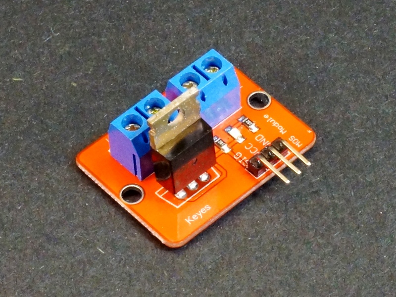
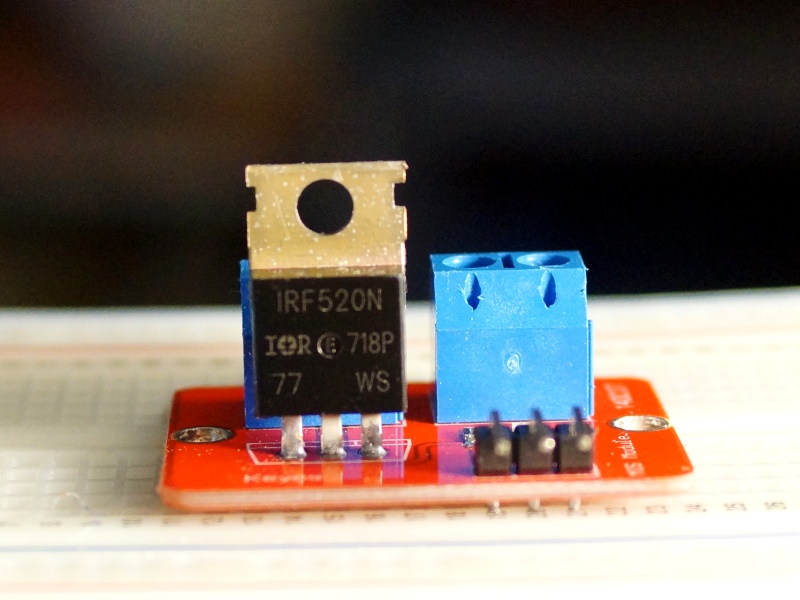
KEY FEATURES OF IRF520 N-CH MOSFET MODULE:
- Switch loads up to 24V @ 5A
- 5V compatible (actually semi-compatible. See notes below)
The IRF520 is not fully 5V logic compatible but it will work fine for many applications if it is derated to the specs we show here. See our evaluation results down below for more detail on that aspect of the module.
These modules can be used to control motors, fans, LEDs and other devices.
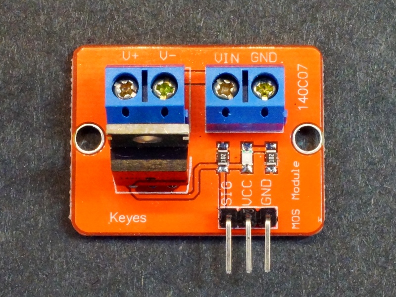
Module Connections
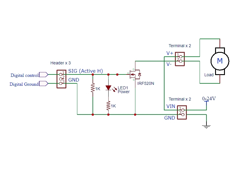
The connectors can look a bit confusing at first, but hook-up is fairly straight forward. The attached schematic can help clarify things.
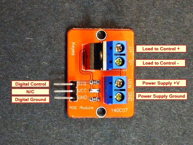
To hook-up:
- Connect the load to be controlled across the V+ and V- terminals observing the correct polarity.
- Connect the power supply (up to 24V) across the Vin and GND terminals.
- Connect the uC ground and control pin to the GND and SIG header pins on the module. The center pin on the header marked ‘VCC’ is not connected.
The ‘SIG’ control input is active HIGH and 5V compatible, but can be driven as high as 10V to drive the IRF520 into full saturation. There is a green LED that lights when SIG is active HIGH
A 1K pull-down resistor is included on the module to help to ensure that the transistor will be in the off state when the microcontroller is powering up and the outputs are floating.
1 x 3 Male Header
- SIG = Signal input (active HIGH). Typically used with 5V logic. Can be driven at up to 10V to fully turn on the IRF520.
- VCC = No connection
- GND = Digital ground.
1 x 2 Screw Terminal (Load)
- V+ = Connect to positive lead of load (motor, LEDs, fan, etc)
- V- = Connect to negative lead of load
1 x 2 Screw Terminal (Power)
- VIN = Connect to power supply (0-24V) being used to power the load
- GND = Connect to power supply ground