Description
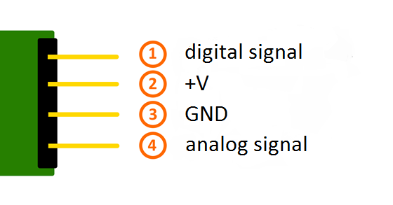
Pinout
Functionality of the sensor
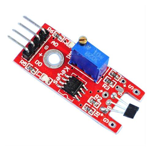
The sensor has 3 main components on its circuit board. First, the sensor unit at the front of the module which measures the area physically and sends an analog signal to the second unit, the amplifier. The amplifier amplifies the signal, according to the resistant value of the potentiometer, and sends the signal to the analog output of the module.
The third component is a comparator which switches the digital out and the LED if the signal falls under a specific value.
You can control the sensitivity by adjusting the potentiometer.
Please notice: The signal will be inverted; that means that if you measure a high value, it is shown as a low voltage value at the analog output.

This sensor doesn’t show absolute values (like exact temperature in °C or magneticfield strenght in mT).
It is a relative measurement: you define an extreme value to a given normal environment situation and a signal will be send if the measurement exceeds the extreme value.
Code example Arduino
The program reads the current voltage value which will be measured at the output pin and shows it via serial interface.
Additionally, the status of the digital pin will be shown at the terminal.
|
1
2
3
4
5
6
7
8
9
10
11
12
13
14
15
16
17
18
19
20
21
22
23
24
25
26
27
28
29
30
31
32
33
34
35
36
37
38
|
// Declaration and initialization of the input pinint Analog_Eingang = A0; // X-axis-signalint Digital_Eingang = 3; // Buttonvoid setup (){pinMode (Analog_Eingang, INPUT);pinMode (Digital_Eingang, INPUT);Serial.begin (9600); // Serielle output with 9600 bps}// The program reads the current value of the input pins// and output it via serial outvoid loop (){float Analog;int Digital;// Current value will be read and converted to the voltageAnalog = analogRead (Analog_Eingang) * (5.0 / 1023.0); Digital = digitalRead (Digital_Eingang);// and outputted hereSerial.print ("Analog voltage value:"); Serial.print (Analog, 4); Serial.print ("V, ");Serial.print ("Extreme value:");if(Digital==1){Serial.println (" reached");}else{Serial.println (" not reached yet");}Serial.println ("----------------------------------------------------------------");delay (200);} |
Connections Arduino:
| digital signal | = | [Pin 3] |
| +V | = | [Pin 5V] |
| GND | = | [Pin GND] |
| analog signal | = | [Pin 0] |
Code example Raspberry Pi
!! Attention !! Analog Sensor !! Attention !!
Unlike the Arduino, the Raspberry Pi doesn’t provide an ADC (Analog Digital Converter) on its Chip. This limits the Raspbery Pi if you want to use a non digital Sensor.
To evade this, use our Sensorkit X40 with the KY-053 module, which provides a 16 Bit ADC, which can be used with the Raspberry Pi, to upgrade it with 4 additional analog input pins. This module is connected via I2C to the Raspberry Pi.
It measures the analog data and converts it into a digital signal which is suitable for the Raspberry Pi.
So we recommend to use the KY-053 ADC if you want to use analog sensors along with the Raspberry Pi.
For more information please look at the infosite: KY-053 Analog Digital Converter
!! Attention !! Analog Sensor !! Attention !!
The program uses the specific ADS1x15 and I2C python-libraries from the company Adafruit to control the ADS1115 ADC. You can find these here: [https://github.com/adafruit/Adafruit-Raspberry-Pi-Python-Code] published under the BSD-License [Link]. You can find the needed libraries in the lower download package.
The program reads the current values of the input pins and outputs it at the terminal in [mV].
Additional to that, the status of the digital pin will be shown at the terminal to show if the extreme value was exceeded or not.
|
1
2
3
4
5
6
7
8
9
10
11
12
13
14
15
16
17
18
19
20
21
22
23
24
25
26
27
28
29
30
31
32
33
34
35
36
37
38
39
40
41
42
43
44
45
46
47
48
49
50
51
52
53
54
55
56
57
58
59
60
61
62
63
64
65
66
67
68
69
70
71
72
73
74
75
76
77
78
79
80
81
82
83
84
85
86
|
################################################################################################################ Copyright by Joy-IT### Published under Creative Commons Attribution-NonCommercial-ShareAlike 3.0 Unported License### Commercial use only after permission is requested and granted###### KY-053 Analog Digital Converter - Raspberry Pi Python Code Example################################################################################################################# This code is using the ADS1115 and the I2C Python Library for Raspberry Pi# This was published on the following link under the BSD licensefrom Adafruit_ADS1x15 import ADS1x15from time import sleep# import needed modulesimport math, signal, sys, osimport RPi.GPIO as GPIOGPIO.setmode(GPIO.BCM)GPIO.setwarnings(False)# initialise variablesdelayTime = 0.5 # in Sekunden# assigning the ADS1x15 ADCADS1015 = 0x00 # 12-bit ADCADS1115 = 0x01 # 16-bit# choosing the amplifing gaingain = 4096 # +/- 4.096V# gain = 2048 # +/- 2.048V# gain = 1024 # +/- 1.024V# gain = 512 # +/- 0.512V# gain = 256 # +/- 0.256V# choosing the sampling rate# sps = 8 # 8 Samples per second# sps = 16 # 16 Samples per second# sps = 32 # 32 Samples per secondsps = 64 # 64 Samples per second# sps = 128 # 128 Samples per second# sps = 250 # 250 Samples per second# sps = 475 # 475 Samples per second# sps = 860 # 860 Samples per second# assigning the ADC-Channel (1-4)adc_channel_0 = 0 # Channel 0adc_channel_1 = 1 # Channel 1adc_channel_2 = 2 # Channel 2adc_channel_3 = 3 # Channel 3# initialise ADC (ADS1115)adc = ADS1x15(ic=ADS1115)# Input pin for the digital signal will be picked hereDigital_PIN = 24GPIO.setup(Digital_PIN, GPIO.IN, pull_up_down = GPIO.PUD_OFF) ############################################################################################################# # ######### main program loop# ######### The program reads the current value of the input pin# and shows it at the terminal try: while True: #Current values will be recorded analog = adc.readADCSingleEnded(adc_channel_0, gain, sps) # Output at the terminal if GPIO.input(Digital_PIN) == False: print "Analog voltage value:", analog,"mV, ","extreme value: not reached" else: print "Analog voltage value:", analog, "mV, ", "extreme value: reached" print "---------------------------------------" sleep(delayTime) except KeyboardInterrupt: GPIO.cleanup() |
Connections Raspberry Pi:
Sensor
| digital signal | = | GPIO 24 | [Pin 18 (RPi)] |
| +V | = | 3,3V | [Pin 1 (RPi)] |
| GND | = | GND | [Pin 06 (RPi)] |
| analog signal | = | Analog 0 | [Pin A0 (ADS1115 – KY-053)] |
ADS1115 – KY-053:
| VDD | = | 3,3V | [Pin 01] |
| GND | = | GND | [Pin 09] |
| SCL | = | GPIO03 / SCL | [Pin 05] |
| SDA | = | GPIO02 / SDA | [Pin 03] |
| A0 | = | look above | [Sensor: analog signal] |