Description
The PWM Signal Generator Module combines an accurate 0-150kHz PWM generator with pushbutton controls and LCD display that shows frequency and duty cycle.
PACKAGE INCLUDES:
- XY-LPWM or HW-753 PWM Signal Generator Module
KEY FEATURES OF PWM SIGNAL GENERATOR MODULE:
- 0-150kHz output frequency range
- 0-100% duty cycle
- 3-30V operation and output pulse amplitude
- Simple pushbutton interface
- LCD display of frequency and duty cycle
- 5-30mA maximum current output
- Serial TTL interface, 3.3V logic compatible.
This is a nice little module that can be used as a flexible square wave generator for conducting experiments, testing and controlling devices that require a PWM input. Having the display and simple pushbutton interface makes it easy to set. Adding an output driver allows it to drive motors, solenoids, servos, dim LEDs and other pulse applications.
Theory of Operation
The reverse engineered schematics show the basic layout of the module.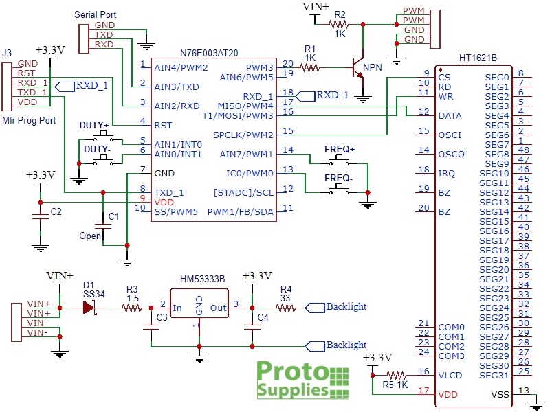
These modules are built with either a Holtek N76E003AT20 or ST Micro STM8S003F3P6 microcontroller and functionality is the same in either case.
The VIN+ input voltage powers a 3.3V linear regulator that supplies 3.3V to the logic circuits on the module.
The microcontroller accepts inputs form the pushbuttons or the TTL serial interface and generates the PWM output signal by using the built-in oscillator and timing circuits of the microcontroller.
The PWM output pin on the microcontroller drives an NPN MMBT3904 type transistor which in turn drives the PWM output pin of the module. The transistor has a series 1K resistor tied to VIN+, so the PWM signal will swing between ground and the module supply voltage on the VIN+ pin.
The 1K resistor limits the maximum available drive current which will vary depending on the VIN+ input voltage and range from about 5mA up to 30mA. This output is suitable fro driving a logic input or to drive a MOSFET transistor if you need to increase the module drive capability. There is also an easy hack to boost the current capability up to about 100mA which is explained down below in Our Evaluation Results section.
Besides the VIN power input connector and PWM output connectors described below, there is a connector on the back of the board labeled J3 which provides access to the programming port of the microcontroller. This is only of interest to anyone thinking about hacking the software on the module.
Note that we may ship boards with fabs marked XY-LWPM or HW-753. The minor functionality differences are noted down below under ‘Our Evaluation Results”
Powering the Module
The module can operate from 3 to 30V power input on the VIN+ connections. The two connections are internally connected and only one needs to be used. Same for VIN- which is the ground connection.
The VIN+ input has a Schottky reverse polarity protection diode. The module logic circuits are powered from a 3.3V regulator, so the VIN+ voltage is usually selected to set the amplitude that is needed for the PWM output. If the PWM output will be used with 5V logic, the module should be powered from 5V.
Below 4V, the LCD backlight will start to dim, but the module will continue to work down to 3V.
The module draws about 20mA from the power source under typical 5V operation.
Setting PWM Frequency
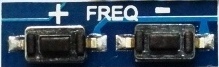 The frequency of the PWM output can be set over the range from 0Hz to 150kHz by pressing the FREQ+ and FREQ- buttons. Holding the buttons down accelerates the frequency change.
When the output is being adjusted, the display shows SET. When no adjustments are being made, it displays OUT.
The current frequency is shown in the upper half of the display with the decimal point indicating the range that is being displayed.
If the display shows XXX, the value is in Hz. A display of 500 indicated 500Hz. The value can be adjusted in increments of 1Hz over the range of 0-999Hz.
If the display shows X.XX, the value is in kHz. A display of 1.00 indicates 1kHz. The value can be adjusted in increments of 10Hz over the range of 1.00kHz – 9.99kHz.
If the display shows XX.X, the value is in tens of kHz. A display of 10.0 indicates 10kHz. The value can be adjusted in increments of 100Hz over the range of 10.0kHz – 99.9kHz.
If the display shows X.X.X, the value is in hundreds of kHz. A display of 1.0.0 indicates 100kHz. The value can be adjusted in increments of 1kHz over the range of 100kHz – 150kHz. This use of multiple decimal points isn’t the most intuitive way to display the value, but it’s not too bad once you get used to it.
Setting PWM Duty Cycle
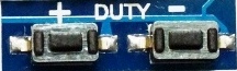 The duty cycle can be set over the range of 0-100% by pushing the DUTY+ and DUTY- buttons. Holding the buttons down accelerates the duty cycle change.
The current duty cycle is shown on the bottom half of the display with a % sign after it.
SERIAL CONTROL INTERFACE
The module has a serial port which provides control over the basic functionality of the module including setting the frequency and duty cycle as well as reading back the current settings.
The serial port is 3.3V compatible, so if using with a 5V MCU, you will need to use a logic level shifter on the module RX line to avoid possible damage.
Communications use 9600 baud rate. As with any serial port, the TX/RX lines are cross-connected, so the MCU TX line connects to the module RX and the MCU RX line connects to the module TX. GND connects to the MCU ground and is not needed if the module power and ground are coming from the MCU.
The communications protocol is very basic as described below.
Setting Frequency
Fxxx = Set Frequency
To set the frequency you send the data in the same format that it is displayed on the LCD proceeded by an upper case ‘F’.
‘F100‘ = Frequency set to 100Hz
‘F1.00‘ = Frequency set to 1kHz
‘F10.0‘ = Frequency set to 10kHz
‘F1.0.0‘ = Frequency set to 100kHz
The module responds with ‘DOWN‘ if the command was understood and ‘FAIL‘ if it wasn’t, such as if the command was formatted incorrectly.
Setting Duty Cycle
Dxxx = Set Duty Cycle
To set the duty cycle, you send the desired duty cycle preceeded by an upper case ‘D’.
‘D050‘ = Duty cycle set to 50%
Reading Current Settings
To read the current settings, you send a lower case ‘read‘.
The module will respond with the frequency and duty cycle like this:
F1.00
D050
or it may report
F=1.00KHz D= 50%
MODULE CONNECTIONS
The connections to the module are straightforward with power on the upper left side, serial connections on lower left side and PWM output on the right side.
Note that the VIN+, VIN-, PWM and PWM GND connections have two connection points each. These are all connected internally, so only 1 pin of each needs to be connected. The grounds are also all in common.
- VIN+= Power 3 to 30V (x2)
- VIN- = Ground (x2)
- PWM = PWM Output (x2)
- GND = PWM Ground (x2)
Serial Port (labeled on backside)
- GND = Serial Ground
- TXD = Transmit Data out of the module. Connects to MCU RXD
- RXD = Receive Data into the module. Connects to MCU TXD
Module Assembly
The module has 4 M2 size holes in the four corners for mounting if desired.
This module does not come with any headers, but they can be ordered separately if needed.
Modules with the marking XY-LPWM
- Pressing and holding the FREQ or DUTY buttons cause the output of the module to change as the display changes
- Serial read will return with the data formatted like this:
F1.00
D050 - Bad serial commands report ‘FAIL’
Modules with the marking HW-753
- Pressing and holding the FREQ or DUTY buttons cause the output of the module to change as the display changes
- Serial read will return with the data formatted like this:
F=1.00KHz D= 50% - Bad serial commands report ‘FALL’, but not in all cases.
Modules with the marking LPWM
- Pressing and holding the FREQ or DUTY buttons do not cause a change on the output until the button is released. The output then changes after about 1 second delay.
- Serial port does not appear to be operational.
Output Drive Limitations
The most likely issue to run into with these modules is trying to drive too large a load and have the output amplitude decrease too much due to the voltage drop through the 1K resistor R2. This resistor is selected to provide safe operation over the wide input voltage range. At 30V, it can pass 30mA and dissipate up to 0.9W which is why it is a physically large resistor.
For driving a logic input, this is not an issue since the current requirements are small, but if you are trying to get a little more drive from it without having to resort to hanging a MOSFET on the output there are some things you can do.
For a dedicated application where you know what voltage you will be using it with, such as 5V, R2 can be replaced or paralleled with a lower value resistor to increase the current handling capability and decrease the voltage drop through it.
The maximum current limitation depends on the current capability of the small transistor which is typically a MMBT3904 that can handle up to 200mA max continuous but is best kept down around 100mA to be on the safe side. A 50 ohm 1/2W resistor would work in this case to provide up to 100mA of drive at 5V.
Output Accuracy
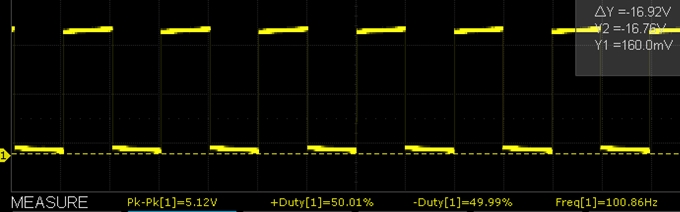
The accuracy is pretty good. On a sample basis we measured the following.
- 100Hz / 50% duty cycle measured 100.86Hz with 50.01% / 49.99% duty cycle
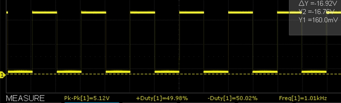
- 1kHz / 50% duty cycle measured 1.01kHz with 49.98% / 50.02% duty cycle
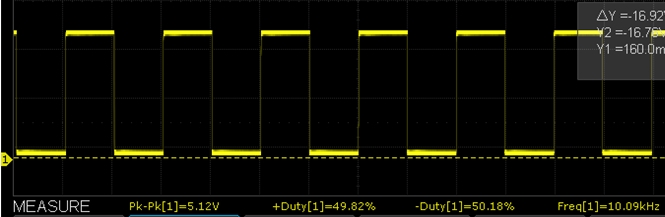
- 10kHz / 50% duty cycle measured 10.09kHz with 49.82% / 50.18% duty cycle
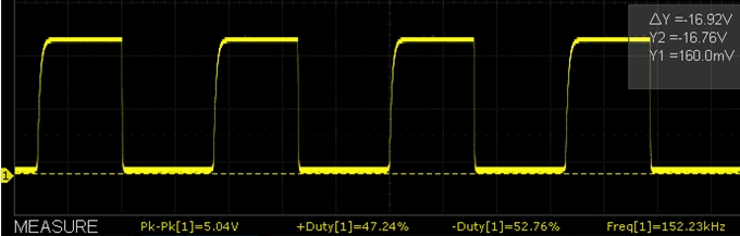
- 150kHz / 50% duty cycle measured 152.233kHz with 47.24% / 52.76% duty cycle
Below are some O’scope waveform captures showing typical performance at these same frequencies.
PWM Signal Generator Control Test Program
/*  Simple program to exercise the PWM Module serial port

Uses hardware serial to talk to the host computer and software serial for
communication with the PWM module for compatibility with any MCU

Connections
  MCU 5V to module VIN+
  MCU GND to module VIN-
  MCU D11 to module RXD using a logic level shifter or voltage divider
  MCU D10 to module TXD

  When a command is entered in the Serial Monitor on the computer, the MCU will
  relay it to the PWM module and echo it to the Serial Monitor window.

  Note that frequency and duty cycle are upper case i.e. 'F100' or 'D050'
  The 'read' query on the other hand is lower case.

  Ensure that Serial Monitor Window is set for 9600 and 'No line ending'

  Any characters returned from the module will be displayed in the Serial Monitor Window.

  Uses Softserial.h library.  Can use hardware serial port if MCU supports it
*/
#include <SoftwareSerial.h>
SoftwareSerial SoftSerial(10, 11); // RX | TX pins.  Can be reassigned if needed

const long BAUDRATE = 9600;    // Baud rate of the XY-LPWM module
char c = ' ';                  // Character being transmitted
//===============================================================================
//  Initialization
//===============================================================================
void setup()
{
    SoftSerial.begin(BAUDRATE);  // Init soft serial object
    Serial.begin(9600);          // Init hardware serial
    Serial.println("PWM Module Serial Test");
    Serial.println("Enter 'Fxxx', 'Fx.xx', 'Fxx.x' or 'Fx.x.x' to set frequency");
    Serial.println("Enter 'Dxxx' to set duty cycle");
    Serial.println("Enter 'read' to get current settings");
}
//===============================================================================
//  Main
//===============================================================================
void loop()
{
     // Watch for any characters returned from module
    if (SoftSerial.available())
    {
        c = SoftSerial.read();
        if (c=='F' || c=='D') Serial.write(' ');  // Add space between commands
        Serial.write(c);
    }
     // Read char from the Serial Monitor and send to the XY-LPWM module
    if (Serial.available())
    {
        c = Serial.read();
        SoftSerial.write(c);
        Serial.write(c);  // Echo character typed to serial monitor window
    }
}
Notes:
- The module may have solder flux on the pins of the LCD module. It is not recommended to clean as the cleaning fluid can easily get under the LCD module where it will be optically visible as a blotchiness in the backlighting and it can be difficult or impossible to remove.
TECHNICAL SPECIFICATIONS
| Operational Ratings | ||
| Vcc | Range | 3 – 30V (3.3 or 5V typical) |
| Frequency | Specified Range | 0 – 150kHz |
| Duty Cycle | 0 – 100% | |
| PWM Pulse Amplitude | Same as VIN+ | |
| Dimensions | L x W x H | 52 x 32 x 10mm (2.05 x 1.26 x 0.39″) |
| Datasheets | Nuvoton microcontroller | N76E003 |
| ST Micro microcontroller | STM8S003F3 | |
| Holtek LCD controller | HT1621 |