Step 1: Items you need to buy
1x Arduino UNO
1x Color Sensor
1x Breadboard
1x RGB Led

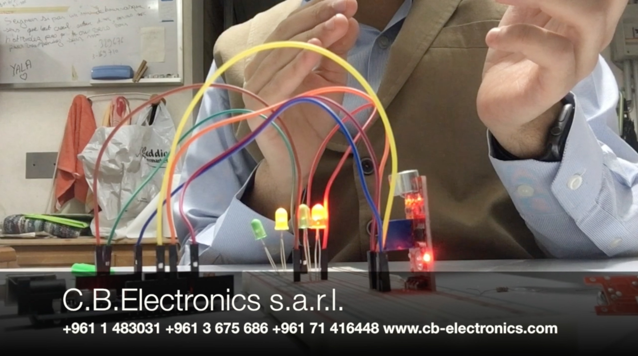
Step 2: Connections
Connect the following pins together properly:
Color Sensor:
S0 <-> PIN 3
S1 <-> PIN 4
S2 <-> PIN 5
S3 <-> PIN 6
Out <-> PIN 2
Vcc <-> 5V
GND <-> GND
RGB Led:
Red <-> PIN 10
Green <-> PIN 9
Blue <-> PIN 8
Step 3: Upload the following code to your Arduino
int s0=3,s1=4,s2=5,s3=6;

int r=10, g=9, b=8;

int out=2;

int flag=0;

byte counter=0;

byte countR=0,countG=0,countB=0;

void setup()

 {

 Serial.begin(115200);

 pinMode(s0,OUTPUT);

 pinMode(s1,OUTPUT);

 pinMode(s2,OUTPUT);

 pinMode(s3,OUTPUT);

 }

void TCS()

 {

 delay(2000);

 flag=0;

 digitalWrite(s1,HIGH);

 digitalWrite(s0,HIGH);

 digitalWrite(s2,LOW);

 digitalWrite(s3,LOW);

 attachInterrupt(0, ISR_INTO, CHANGE);

 timer0_init();

 }

void ISR_INTO()

 {

 counter++;

 }

 void timer0_init(void)

 {

  TCCR2A=0x00;

  TCCR2B=0x07;   //the clock frequency source 1024 points

  TCNT2= 100;    //10 ms overflow again

  TIMSK2 = 0x01; //allow interrupt

 }

 int i=0;

 ISR(TIMER2_OVF_vect)//the timer 2, 10ms interrupt overflow again. Internal overflow interrupt executive function

{

    TCNT2=100;

    flag++;

 if(flag==1)

  {

    countR=counter;

    Serial.print("red=");

    Serial.println(countR,DEC);

    digitalWrite(s2,HIGH);

    digitalWrite(s3,HIGH);

    analogWrite(r, countR);

    analogWrite(g, countG);

    analogWrite(b, countB);

  }

  else if(flag==2)

   {

    countG=counter;

    Serial.print("green=");

    Serial.println(countG,DEC);

    digitalWrite(s2,LOW);

    digitalWrite(s3,HIGH);

    analogWrite(r, countR);

    analogWrite(g, countG);

    analogWrite(b, countB);

   }

   else if(flag==3)

    {

    countB=counter;

    Serial.print("blue=");

    Serial.println(countB,DEC);

    Serial.println("\n");

    digitalWrite(s2,LOW);

    digitalWrite(s3,LOW);

    analogWrite(r, countR);

    analogWrite(g, countG);

    analogWrite(b, countB);


    }

    else if(flag==4)

     {

     flag=0;

     }

       counter=0;

}

void loop()

 {

  TCS();

while(1);

 }
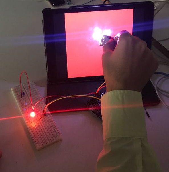
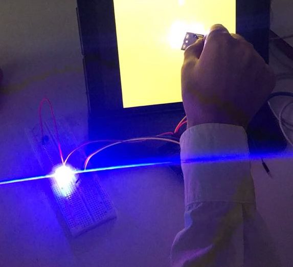
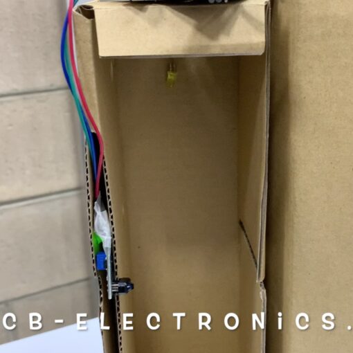
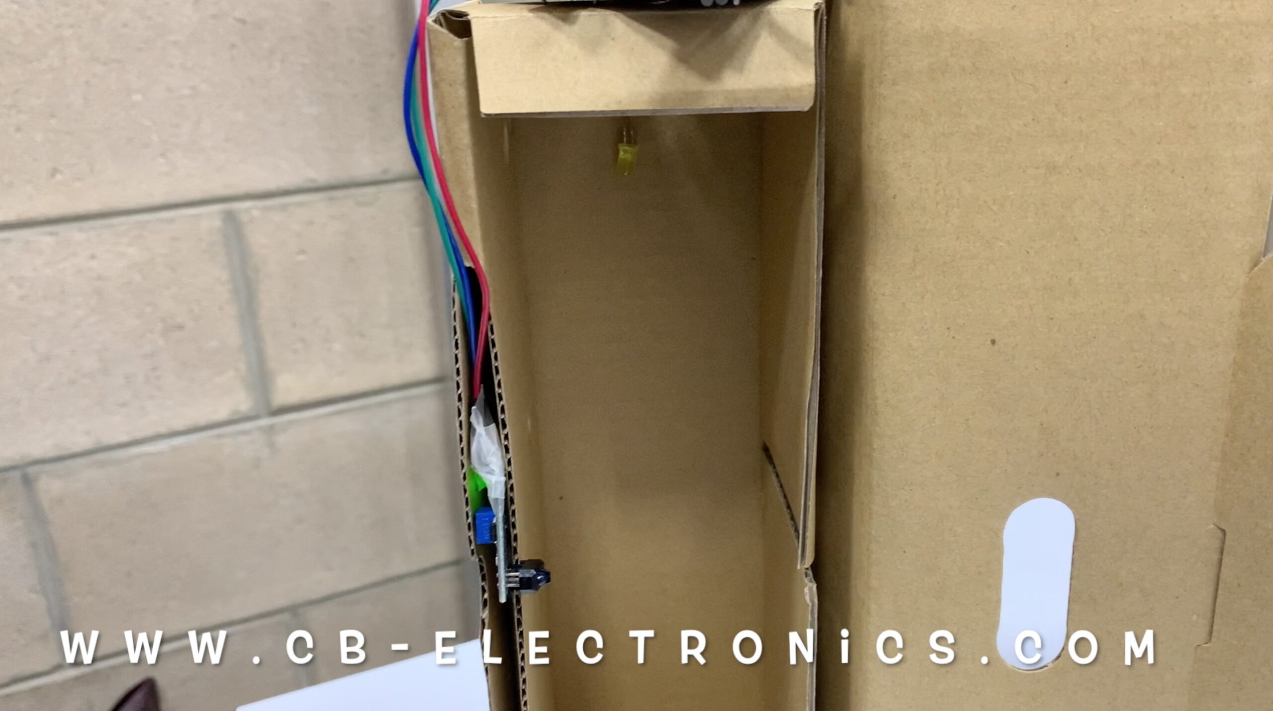
Step 4: Test the sensor
To obtain more precise results, you should put the sensor inside black box. Test the project, and share with us the results.
