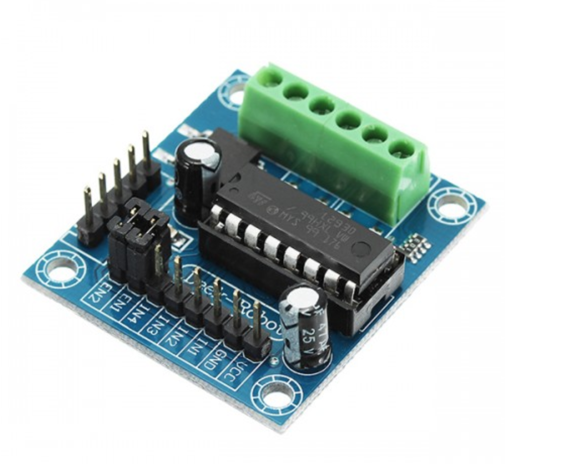
Description
Input voltage DC4.5-25V,
600mA output current capability per channel
1.2A PEAK output current(non repetitive) per channel
Enable facility
Overtemperature protection
Logical “0” input voltage up to 1.5 V(HIGH NOISE IMMUNITY)
Internal clamp diodes
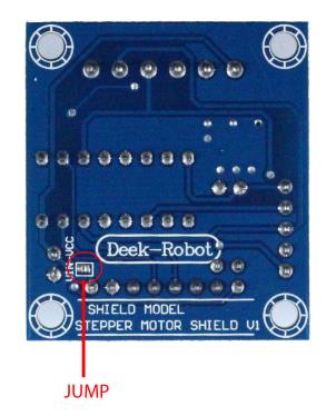
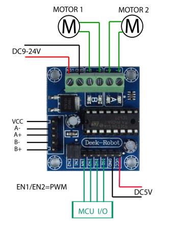
9-24V motor drive wiring:
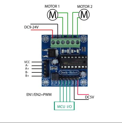
5V motor drive wiring: