LED MATRIX 4 IN 1 – MAX7219 Red LED Dot Matrix Display Module MCU Control DIY Kit for Arduino

  • The MAX7219 is an integrated serial input/output common-cathode display driver that connects a microprocessor to an 8-digit digital 7-segment LED display, or a bar graph display or 64 separate LEDs.
  • It includes an on-chip B-type BCD encoder, multi-channel scan loop, segment word driver, and an 8×8 static RAM to store each data. Only one external register is used to set the segment current of each LED.
  • A convenient four-wire serial interface can be connected to all common microprocessors. Each data can be addressed without any need to overwrite all displays when updating. The MAX7219 also allows the user to choose whether to encode or not encode each data.
  • The entire device includes a 150μA low-power shutdown mode, analog and digital brightness control, a scan limit register that allows the user to display 1-8 bits of data, and a detection mode that allows all LEDs to illuminate.
Categories: , Tags: , , ,

Module parameters:
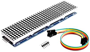
1. A single module can drive an 8×8 common cathode matrix
2. Module working voltage: 5V
3. Module size: length 12.8 cm X width 3.2 cm X height 1.3 cm
4. With 16 fixing screw holes, aperture 3mm
5. Module with input and output interface, support multiple module cascade
6. Color: red, green, blue

Wiring instructions:
1. The left side of the module is the input port, and the right side is the output port.
2. When controlling a single module, you only need to connect the input port to the CPU.
3. When multiple modules are cascaded, the input of the first module is connected to the CPU, the output is connected to the input of the second module, the output of the second module is connected to the input of the third module, and so on.
Take 51 MCU as an example:
VCC → 5V
GND → GND
DIN → P2.2
CS → P2.1
CLK → P2.0

Package Included:
1pcs NOYITO MAX7219 Dot Matrix Module 4 in 1 Display Module
1pcs 20cm 5P DuPont line