Description
ATWINC1510-MR210PB FEATURES
The ATWINC1510-MR210PB is a low-power consumption 802.11 b/g/n module which is specifically optimized for low-power IoT applications.
The module has a Cortus APS3 32-bit processor. This processor performs many of the MAC functions, including but not limited to association, authentication, power management, security key management, and MSDU aggregation/de-aggregation. In addition, the processor provides flexibility for various modes of operation, such as STA and AP modes.
MODULE CURRENT CONSUMPTION
The table below describes the current consumption of the ATWINC1510-MR210PB module:
| Device state | Code rate | Output power, dBm | Current consumption(1) | |
|---|---|---|---|---|
| IVBATT | IVDDIO | |||
| ON_Transmit | 802.11b 11Mbps | 20.5 | 290mA | 22mA |
| 802.11b 11Mbps | 19.5 | 294mA | 22mA | |
| 802.11g 6Mbps | 19.5 | 292mA | 22mA | |
| 802.11b 54Mbps | 17.5 | 250mA | 22mA | |
| 802.11n MCS 0 | 18.0 | 244mA | 22mA | |
| 802.11n MCS 7 | 15.5 | 289mA | 22mA | |
| ON_Receive | 802.11b 1Mbps | N/A | 52.5mA | 22mA |
| 802.11b 11Mbps | N/A | 52.5mA | 22mA | |
| 802.11g 6Mbps | N/A | 55.0mA | 22mA | |
| 802.11b 54Mbps | N/A | 57.5mA | 22mA | |
| 802.11n MCS 0 | N/A | 54.0mA | 22mA | |
| 802.11n MCS 7 | N/A | 58.5mA | 22mA | |
| ON_Doze | N/A | N/A | 380µA | <3.5µA |
| Power_Down | N/A | N/A | <0.5µA | <3.5µA |
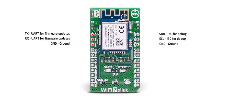
ADDITIONAL PINS
Additional pins on the WiFi 7 click, besides the ones on the mikroBUS™ line:
SPECIFICATIONS
| Type | WiFi |
| Applications | Optimized for low power IoT applications |
| On-board modules | ATWINC1510-MR210PB |
| Key Features | IEEE® 802.11 b/g/n 20MHz solution, integrated PCB antenna, supports IEEE 802.11 WEP, WPA, WPA2 Security |
| Interface | GPIO,SPI |
| Compatibility | mikroBUS |
| Click board size | M (42.9 x 25.4 mm) |
| Input Voltage | 3.3V |
PINOUT DIAGRAM
This table shows how the pinout on WiFi 7 click corresponds to the pinout on the mikroBUS™ socket (the latter shown in the two middle columns).
| Notes | Pin | Pin | Notes | ||||
|---|---|---|---|---|---|---|---|
| NC | 1 | AN | PWM | 16 | EN | Module Enable | |
| Active-Low Hard Reset | RST | 2 | RST | INT | 15 | INT | Device Interrupt output |
| Chip select | CS | 3 | CS | TX | 14 | NC | |
| SPI Clock | SCK | 4 | SCK | RX | 13 | NC | |
| SPI Master Input Slave Output | MISO | 5 | MISO | SCL | 12 | NC | |
| SPI Master Output Slave Input | MOSI | 6 | MOSI | SDA | 11 | NC | |
| Power supply | +3.3V | 7 | 3.3V | 5V | 10 | NC | |
| Ground | GND | 8 | GND | GND | 9 | GND | Ground |
PROGRAMMING
Code examples for WiFi 7 click, written for MikroElektronika hardware and compilers are available on Libstock.
CODE SNIPPET
The following code snippet shows the default main function for all examples.
01 void main(void)
02 {
03     systemInit();
04     printf("Project built for Click Boardrn");
05     printf("Starting driver initialization...rn");
06
07     hal_wifi7_init();
08     m2m_wifi_init();
09     while (1)
10     {
11         ApplicationTask();
12         m2m_wifi_task();
13     }
14 }