
Description
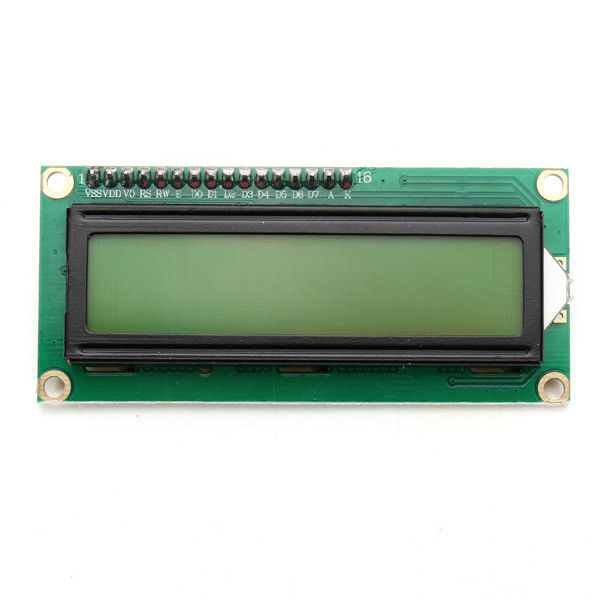
| Pin No | Function | Name |
| 1 | Ground (0V) | Ground |
| 2 | Supply voltage; 5V (4.7V – 5.3V) | Vcc |
| 3 | Contrast adjustment; the best way is to use variable resistor such as a potentiometer. The output of the potentiometer is connected to this pin. Rotate the potentiometer knob forward and backwards to adjust the LCD contrast. | Vo / VEE |
| 4 | Selects command register when low, and data register when high | RS (Register Select ) |
| 5 | Low to write to the register; High to read from the register | Read/write |
| 6 | Sends data to data pins when a high to low pulse is given; Extra voltage push is required to execute the instruction and EN(enable) signal is used for this purpose. Usually, we make it en=0 and when we want to execute the instruction we make it high en=1 for some milli seconds. After this we again make it ground that is, en=0. | Enable |
| 7 | 8-bit data pins | DB0 |
| 8 | DB1 | |
| 9 | DB2 | |
| 10 | DB3 | |
| 11 | DB4 | |
| 12 | DB5 | |
| 13 | DB6 | |
| 14 | DB7 | |
| 15 | Backlight VCC (5V) | Led+ |
| 16 | Backlight Ground (0V) | Led- |
RS(Register select)
A 16X2 LCD has two registers, namely, command and data. The register select is used to switch from one register to other. RS=0 for command register, whereas RS=1 for data register.
Command Register: The command register stores the command instructions given to the LCD. A command is an instruction given to LCD to do a predefined task like initializing it, clearing its screen, setting the cursor position, controlling display etc. Processing for commands happen in the command register.
Data Register: The data register stores the data to be displayed on the LCD. The data is the ASCII value of the character to be displayed on the LCD. When we send data to LCD it goes to the data register and is processed there. When RS=1, data register is selected.