A practical build log, complete wiring guide, calibration notes, and flicker-free display sketch
The MG811 is an interesting solid-electrolyte carbon-dioxide sensor, but it is not a simple “connect analog output to Arduino A0 and read percentage” device. During this project, we learned that the sensor needs a dedicated heater supply, an exceptionally high-impedance measurement circuit, adequate aging and warm-up time, and real calibration before its output can be treated as CO₂ concentration.
This article documents the complete prototype:
- An MG811 CO₂ sensor module
- An Arduino Uno
- A CA3140 high-input-impedance amplifier
- A 1.28-inch, 240×240 round GC9A01 TFT
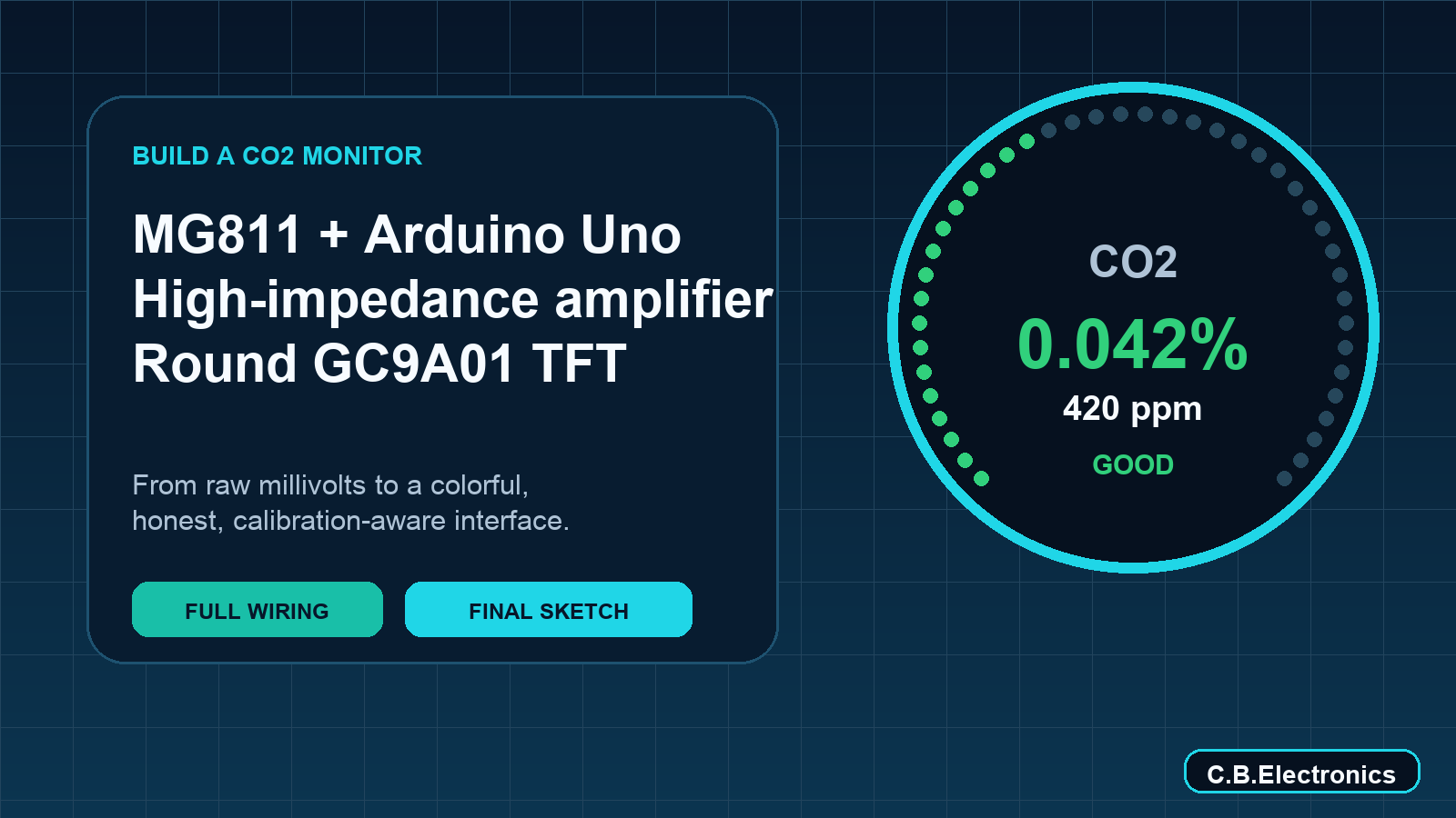
- A circular, color-coded CO₂ interface
- Averaging and filtering to reduce noisy readings
- Incremental screen updates to eliminate visible blinking
Important: This is an experimental educational project, not a certified safety instrument. Never use an uncalibrated MG811 prototype to make life-safety, occupational-safety, medical, or ventilation-control decisions.
1. What the MG811 actually measures
The MG811 generates an electromotive-force signal that changes with CO₂ concentration. According to the official Winsen MG811 manual, the bare sensor has:
- A specified detection range of 350–10,000 ppm CO₂
- A 6.0 V ±0.1 V heater
- Approximately 140 mA heater current
- Approximately 850 mW heater consumption
- A nominal zero-point EMF in the 200–600 mV range
- A test-circuit resistance requirement greater than 100 GΩ
The last point is crucial. A conventional Arduino analog input or ordinary bipolar-input operational amplifier can load the sensing element and disturb the measurement.
Our particular generic module exposed a much smaller AOUT signal than the bare-sensor EMF specification. We observed roughly 8–12 mV before our external amplifier. Module designs differ, so measure the actual module output before selecting amplifier gain.
What “ppm” means
ppm means parts per million. For gas concentration, it is normally a volume ratio:
400 ppm CO₂ = 400 parts CO₂ per 1,000,000 parts of air
The relationship between ppm and actual CO₂ percentage is:
CO₂ percentage = ppm ÷ 10,000
ppm = CO₂ percentage × 10,000
Examples:
REFERENCE
CO₂ concentration: 400 ppm | Actual percentage: 0.040%
CO₂ concentration: 1,000 ppm | Actual percentage: 0.100%
CO₂ concentration: 5,000 ppm | Actual percentage: 0.500%
CO₂ concentration: 10,000 ppm | Actual percentage: 1.000%
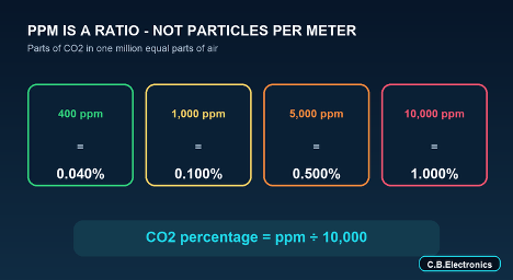
A reading of 100% would mean pure CO₂. The MG811’s specified upper range of 10,000 ppm is only 1% actual CO₂.
2. Why the first direct Arduino readings were nearly zero
With AOUT connected directly to Arduino A0, our readings were typically:
Raw A0: 2–3
Voltage: 0.010–0.015 V
An Arduino Uno uses a 10-bit ADC by default. With a 5 V reference:
ADC step = 5 V ÷ 1023 ≈ 4.89 mV
A 10 mV signal therefore occupies only about two ADC counts. That is far too little resolution for useful measurement.
An early logarithmic conversion produced impossible results such as thousands of percent. The Arduino was not detecting an extraordinary CO₂ concentration; the formula was extrapolating far outside its calibration range.
A quick Arduino ADC test
Before blaming the sensor, disconnect AOUT and test the Arduino input:
A0 connected to GND → reading should be near 0
A0 connected to 5 V → reading should be near 1023
Never short 5 V directly to ground.
3. Choosing an amplifier
Common parts such as the LM741, LM358, and LM324 are poor choices directly at the sensing node.
The LM741 normally requires higher or dual supply rails and cannot operate properly near ground from an Arduino’s 5 V supply. The LM358 and LM324 can operate from a single supply, but their bipolar input currents are undesirable for this unusually high-impedance sensor.
Better choices include:
- LMC6482
- LMC662
- LMC6001
- MCP6001 or MCP6002
- CA3140
- TLC271, TLC272, or TLC277
We used a CA3140 because it was locally available. It has a MOSFET input stage, very high input impedance, and supports single-supply operation. See the CA3140 product documentation.
The CA3140 is acceptable for this prototype, but a modern electrometer-grade or very-low-bias CMOS amplifier is preferable for higher accuracy.
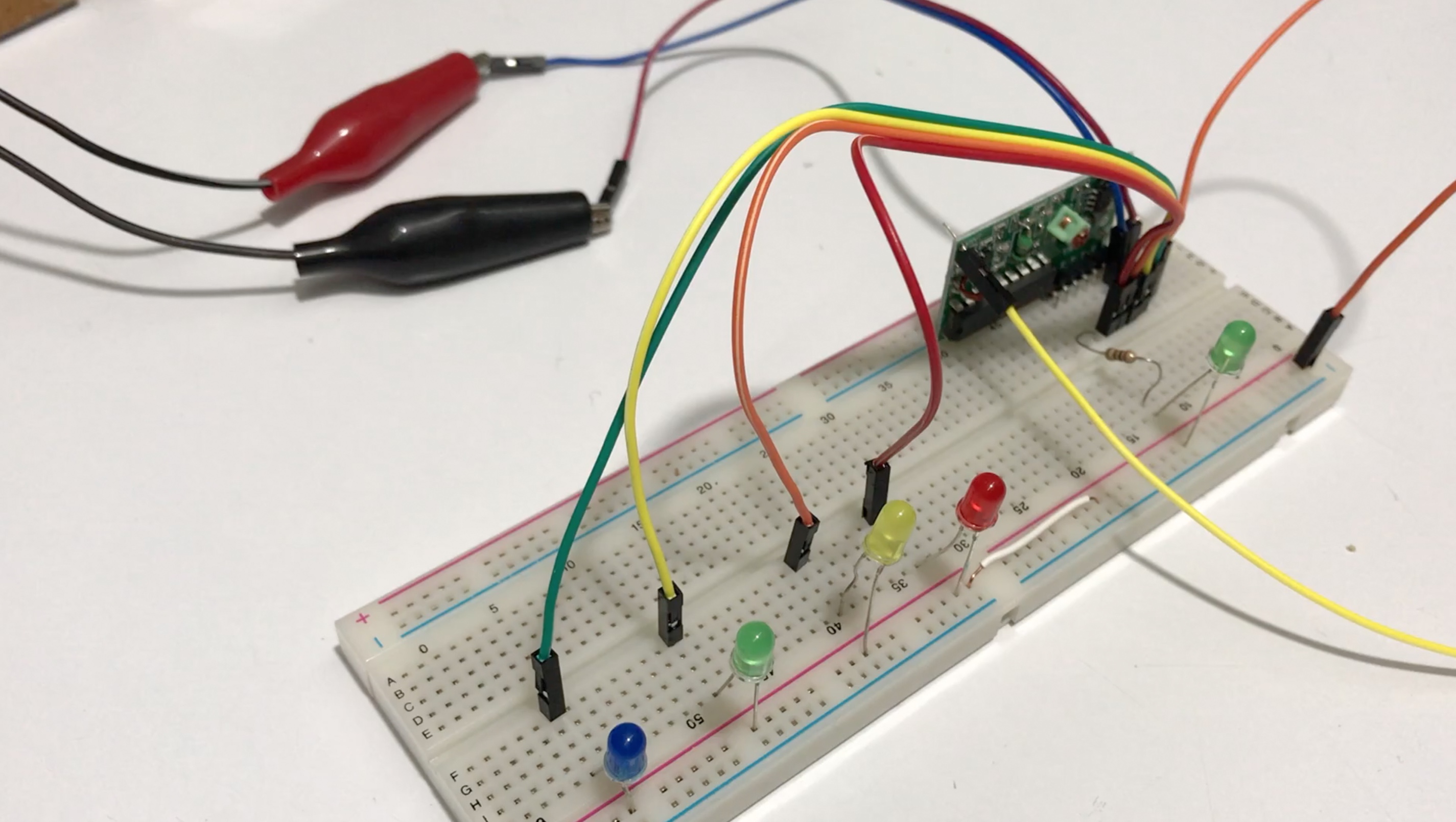
4. CA3140 amplifier circuit
Our module produced a very small analog signal, so we configured the CA3140 as a non-inverting amplifier.
Parts
- 1 × CA3140E, 8-pin DIP
- 1 × 470 kΩ resistor
- 1 × 10 kΩ resistor
- 1 × 100 nF ceramic bypass capacitor
- Optional 1 × 1 kΩ resistor between amplifier output and Arduino A0
Gain
The non-inverting gain is:
Gain = 1 + (Rf ÷ Rg)
Gain = 1 + (470 kΩ ÷ 10 kΩ)
Gain = 48
Example:
10 mV sensor output × 48 ≈ 0.48 V
CA3140 pinout
Viewed from above, with the notch facing upward:
┌─────────┐
Offset Null 1│ │8 Strobe — leave open
− Input 2│ CA3140 │7 +5 V
+ Input 3│ │6 Output
Ground 4│ │5 Offset Null — leave open
└─────────┘
Amplifier wiring
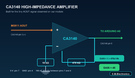
MG811 module AOUT ─────────────────────────→ CA3140 pin 3 (+)
CA3140 pin 6 (output) ── 470 kΩ ──────────→ CA3140 pin 2 (−)
CA3140 pin 2 (−) ── 10 kΩ ───────────→ GND
CA3140 pin 6 ── optional 1 kΩ ─────────────→ Arduino A0
CA3140 pin 7 ──────────────────────────────→ Arduino 5 V
CA3140 pin 4 ──────────────────────────────→ Common GND
100 nF capacitor directly between pins 7 and 4
Pins 1, 5, and 8 left unconnected
The bypass capacitor should be physically close to the CA3140. High-impedance nodes are sensitive to dirt, moisture, fingers, and long breadboard wiring. Keep the connection from AOUT to pin 3 short and clean.
Do not blindly copy the gain
If your module outputs hundreds of millivolts instead of our observed 8–12 mV, a gain of 48 will saturate the amplifier. Start with:
Rf = 100 kΩ
Rg = 10 kΩ
Gain = 11
Measure the amplifier output. Move to a gain of 48 only if the output remains safely below the Arduino’s reference voltage.
5. MG811 power connections
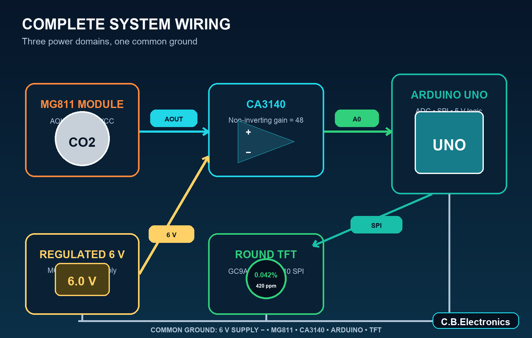
The official bare-sensor specification calls for a 6.0 V heater at approximately 140 mA. Generic breakout modules vary: some require 6 V, while others contain additional power circuitry and accept 5 V. Follow the documentation for the exact module in hand.
For our 6 V module arrangement:
External regulated 6 V positive ──────────→ MG811 module VCC
External regulated 6 V negative ──────────→ MG811 module GND
MG811 module GND ─────────────────────────→ Arduino GND
MG811 module AOUT ────────────────────────→ CA3140 pin 3
The Arduino remains powered through USB. All grounds must be connected, but do not connect the external 6 V positive terminal to Arduino 5 V, A0, or the TFT.
Do not power the MG811 heater from an Arduino GPIO pin.
6. Sensor aging, warm-up, and moisture
A 20-minute warm-up can be useful for a quick functional test, but it is not necessarily enough for a new or long-stored MG811.
The Winsen manual recommends powered aging based on storage duration:
REFERENCE
Previous storage time: Less than one month | Suggested powered aging: At least 48 hours
Previous storage time: One to six months | Suggested powered aging: At least 72 hours
Previous storage time: More than six months | Suggested powered aging: At least 168 hours
This explains why a new sensor can drift for hours even when the wiring is correct.
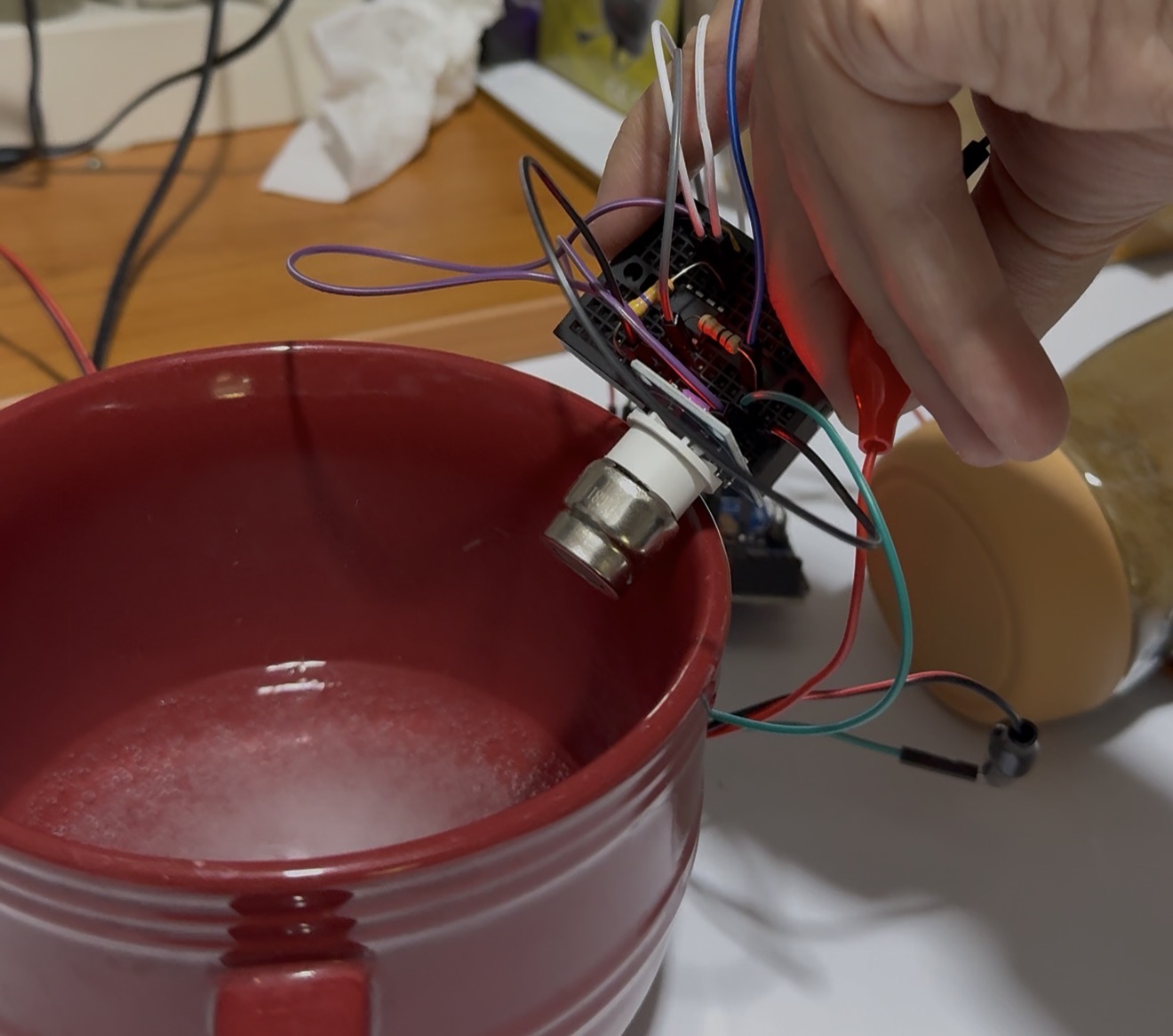
Direct breath is also a poor calibration method. It contains several percent CO₂, but it also carries heat and considerable moisture. The official manual warns that water condensation affects sensor performance.
For a response demonstration:
- Breathe from a distance rather than directly onto the sensing element.
- Keep the exposure brief.
- Return the sensor to gently ventilated room air.
- Expect recovery to take time.
- Never use a hairdryer or strong heat to force recovery.
If moisture exposure causes a long drift, leave the heater powered and place the sensor in clean, gently moving room-temperature air.
7. The round GC9A01 TFT
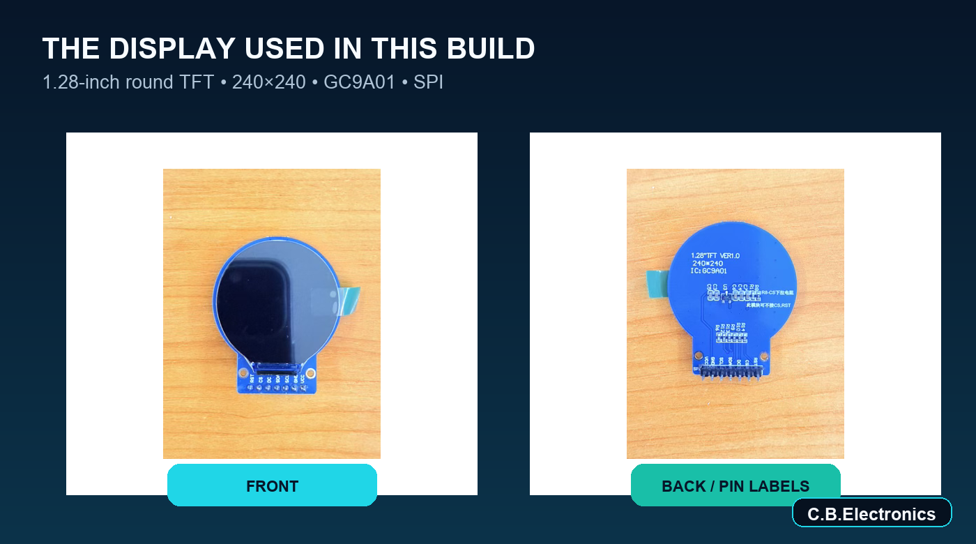
The display used in this build is a 1.28-inch, 240×240 round IPS TFT with a GC9A01 controller. It uses four-wire SPI. The pins marked SDA and SCL are SPI data and clock—not I²C.
The Waveshare GC9A01 module documentation confirms the 240×240 resolution, SPI interface, and Arduino Uno hardware-SPI pins.
TFT-to-Arduino Uno wiring
REFERENCE
TFT pin: GND | Purpose: Ground | Arduino Uno: GND
TFT pin: VCC | Purpose: Display power | Arduino Uno: 5V*
TFT pin: SCL | Purpose: SPI clock | Arduino Uno: D13
TFT pin: SDA | Purpose: SPI MOSI/data | Arduino Uno: D11
TFT pin: RES | Purpose: Reset | Arduino Uno: D8
TFT pin: DC | Purpose: Data/command | Arduino Uno: D9
TFT pin: CS | Purpose: Chip select | Arduino Uno: D10
TFT pin: BLK | Purpose: Backlight | Arduino Uno: 5V*
*Use 5 V only when the exact breakout board is documented as 3.3/5 V compatible. A bare 3.3 V GC9A01 board requires appropriate power and logic-level conversion.
Required Arduino libraries
Install these through Arduino IDE Library Manager:
- Adafruit GC9A01A
- Adafruit GFX Library
- Adafruit BusIO
If compilation reports multiple definitions of Adafruit_SPIDevice, inspect the Arduino libraries folder for accidental files such as:
Adafruit_SPIDevice.cpp
Adafruit_SPIDevice 2.cpp
Delete the corrupted Adafruit_BusIO library folder and reinstall one clean copy through Library Manager.
8. Calibration: the step that cannot be skipped
The relationship between MG811 voltage and the logarithm of CO₂ concentration is approximately linear over a useful region, but every sensor and analog front end has its own offset and slope.
A real two-point calibration requires:
- A known low concentration, preferably certified gas or a trustworthy reference instrument.
- A second known concentration within the intended measurement range.
- Stable temperature, humidity, heater voltage, and sufficient aging time.
Outdoor air may be used as a rough low-point check, but local outdoor concentration is not a certified 420 ppm reference. Exhaled breath is not a suitable high calibration point because its concentration and humidity vary and it exceeds the MG811’s specified upper range.
In the sketch below:
const bool CALIBRATION_VALID = false;
is deliberately the default. In this mode, the display reports the amplified voltage and clearly says CALIBRATE, rather than presenting guessed ppm as fact.
After obtaining two real calibration points:
const float V_AT_LOW_POINT = measured amplified voltage;
const float LOW_POINT_PPM = known concentration;
const float V_AT_HIGH_POINT = measured amplified voltage;
const float HIGH_POINT_PPM = known concentration;
const bool CALIBRATION_VALID = true;
The high-point voltage may be greater or smaller than the low-point voltage depending on whether the module’s onboard circuitry inverts the raw sensor response. The two-point formula handles either direction.
9. Why the first TFT interface blinked
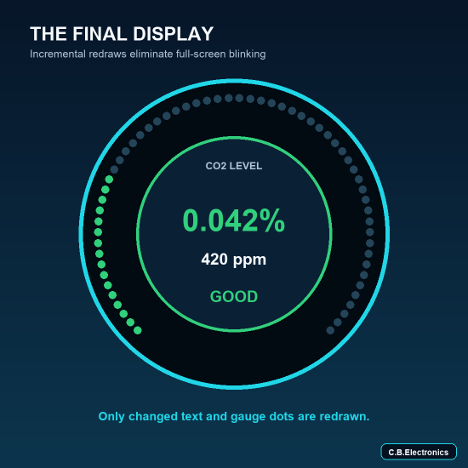
The first graphics version cleared and redrew the center of the display every second. Because the Arduino Uno does not have enough RAM for a full 240×240 16-bit framebuffer, that clear-and-redraw sequence was visible as blinking.
The final version avoids it by:
- Updating the TFT only when the rounded displayed value changes.
- Drawing text with an opaque character background instead of clearing a large area.
- Updating only gauge dots that changed.
- Drawing the static screen elements only once.
10. Final flicker-reduced Arduino sketch
#include <SPI.h>
#include <Adafruit_GFX.h>
#include <Adafruit_GC9A01A.h>
#include <math.h>

#define TFT_CS  10
#define TFT_DC   9
#define TFT_RST  8

Adafruit_GC9A01A tft(TFT_CS, TFT_DC, TFT_RST);

const byte MG811_PIN = A0;

const float ADC_REFERENCE = 5.00;
const float ADC_MAX = 1023.0;
const float AMPLIFIER_GAIN = 48.0;

/*
  Leave this false until two real calibration points have been
  measured. When false, the screen shows voltage and CALIBRATE.
*/
const bool CALIBRATION_VALID = false;

/*
  EXAMPLE PLACEHOLDERS ONLY — replace all four values.
  These voltages are measured at the CA3140 output, not directly
  at the sensor.
*/
const float V_AT_LOW_POINT = 0.437;
const float LOW_POINT_PPM = 420.0;

const float V_AT_HIGH_POINT = 0.457;
const float HIGH_POINT_PPM = 1000.0;

const int SAMPLE_COUNT = 200;
const float FILTER_ALPHA = 0.05;

float filteredVoltage = 0.0;
bool filterStarted = false;

const uint16_t BLACK       = 0x0000;
const uint16_t WHITE       = 0xFFFF;
const uint16_t DARK_BG     = 0x0841;
const uint16_t GAUGE_EMPTY = 0x2945;
const uint16_t CYAN        = 0x07FF;
const uint16_t GREEN       = 0x07E0;
const uint16_t YELLOW      = 0xFFE0;
const uint16_t ORANGE      = 0xFD20;
const uint16_t RED         = 0xF800;
const uint16_t LIGHT_GRAY  = 0xBDF7;

int previousSegments = -1;
uint16_t previousGaugeColor = BLACK;
long previousDisplayKey = -99999;

float readAverageVoltage() {
  unsigned long total = 0;

  for (int i = 0; i < SAMPLE_COUNT; i++) {
    total += analogRead(MG811_PIN);
    delay(2);
  }

  float averageRaw = total / (float)SAMPLE_COUNT;
  return averageRaw * ADC_REFERENCE / ADC_MAX;
}

float voltageToPPM(float voltage) {
  if (!CALIBRATION_VALID) {
    return NAN;
  }

  float voltageDifference =
      V_AT_HIGH_POINT - V_AT_LOW_POINT;

  float logarithmDifference =
      log10(HIGH_POINT_PPM) - log10(LOW_POINT_PPM);

  if (fabs(voltageDifference) < 0.0001 ||
      fabs(logarithmDifference) < 0.0001) {
    return NAN;
  }

  float slope =
      voltageDifference / logarithmDifference;

  float intercept =
      V_AT_LOW_POINT -
      slope * log10(LOW_POINT_PPM);

  float ppm =
      pow(10.0, (voltage - intercept) / slope);

  if (!isfinite(ppm)) {
    return NAN;
  }

  return constrain(ppm, 0.0, 10000.0);
}

void printCentered(
  const char *text,
  int16_t centerX,
  int16_t y,
  uint8_t textSize,
  uint16_t color
) {
  int16_t x1;
  int16_t y1;
  uint16_t width;
  uint16_t height;

  tft.setTextSize(textSize);
  tft.setTextColor(color);
  tft.setTextWrap(false);
  tft.getTextBounds(
    text, 0, y, &x1, &y1, &width, &height
  );

  tft.setCursor(centerX - width / 2, y);
  tft.print(text);
}

void printCenteredOpaque(
  const char *text,
  int16_t centerX,
  int16_t y,
  uint8_t textSize,
  uint16_t color,
  uint16_t background
) {
  int16_t x1;
  int16_t y1;
  uint16_t width;
  uint16_t height;

  tft.setTextSize(textSize);
  tft.setTextColor(color, background);
  tft.setTextWrap(false);
  tft.getTextBounds(
    text, 0, y, &x1, &y1, &width, &height
  );

  tft.setCursor(centerX - width / 2, y);
  tft.print(text);
}

uint16_t getLevelColor(float ppm) {
  if (!isfinite(ppm)) return CYAN;
  if (ppm < 800.0) return GREEN;
  if (ppm < 1200.0) return YELLOW;
  if (ppm < 2000.0) return ORANGE;
  return RED;
}

const char *getAirStatus(float ppm) {
  if (!isfinite(ppm)) return "CALIBRATE";
  if (ppm < 800.0) return "GOOD     ";
  if (ppm < 1200.0) return "MODERATE ";
  if (ppm < 2000.0) return "HIGH     ";
  return "VERY HIGH";
}

void drawGaugeDot(int index, uint16_t color) {
  const int centerX = 120;
  const int centerY = 120;
  const int radius = 105;
  const int segments = 60;

  float angleDegrees =
      135.0 + (270.0 * index / (segments - 1));

  float angleRadians =
      angleDegrees * PI / 180.0;

  int x = centerX + cos(angleRadians) * radius;
  int y = centerY + sin(angleRadians) * radius;

  tft.fillCircle(x, y, 4, color);
}

void updateGauge(float ppm) {
  const int segments = 60;

  int activeSegments = 0;
  uint16_t levelColor = getLevelColor(ppm);

  if (isfinite(ppm)) {
    float progress =
        constrain(ppm / 2000.0, 0.0, 1.0);

    activeSegments =
        round(progress * segments);
  }

  if (previousSegments < 0 ||
      levelColor != previousGaugeColor) {
    for (int i = 0; i < segments; i++) {
      drawGaugeDot(
        i,
        i < activeSegments
          ? levelColor
          : GAUGE_EMPTY
      );
    }
  } else if (activeSegments > previousSegments) {
    for (int i = previousSegments;
         i < activeSegments;
         i++) {
      drawGaugeDot(i, levelColor);
    }
  } else if (activeSegments < previousSegments) {
    for (int i = activeSegments;
         i < previousSegments;
         i++) {
      drawGaugeDot(i, GAUGE_EMPTY);
    }
  }

  previousSegments = activeSegments;
  previousGaugeColor = levelColor;
}

void drawStaticScreen() {
  tft.fillScreen(BLACK);

  tft.drawCircle(120, 120, 116, CYAN);
  tft.drawCircle(120, 120, 115, DARK_BG);
  tft.fillCircle(120, 120, 79, DARK_BG);

  printCentered(
    "MG811 CO2", 120, 28, 2, CYAN
  );

  printCentered(
    "CO2 LEVEL", 120, 70, 1, LIGHT_GRAY
  );

  printCentered(
    "0", 29, 189, 1, LIGHT_GRAY
  );

  printCentered(
    "2000", 208, 189, 1, LIGHT_GRAY
  );

  tft.drawCircle(120, 120, 78, CYAN);
  tft.drawCircle(120, 120, 79, CYAN);
}

void updateDisplay(float ppm, float voltage) {
  long displayKey;

  if (isfinite(ppm)) {
    displayKey = (long)round(ppm / 25.0);
  } else {
    // Update uncalibrated voltage in 1 mV steps.
    displayKey = -(long)round(voltage * 1000.0);
  }

  if (displayKey == previousDisplayKey) {
    return;
  }

  char mainText[14];
  char secondText[14];

  uint16_t levelColor = getLevelColor(ppm);

  if (isfinite(ppm)) {
    float displayedPPM = displayKey * 25.0;
    float percentage = displayedPPM / 10000.0;

    char percentageNumber[12];

    dtostrf(
      percentage, 6, 3, percentageNumber
    );

    snprintf(
      mainText,
      sizeof(mainText),
      "%s%%",
      percentageNumber
    );

    snprintf(
      secondText,
      sizeof(secondText),
      "%5d ppm",
      (int)displayedPPM
    );

    updateGauge(displayedPPM);
  } else {
    char voltageNumber[12];

    dtostrf(
      voltage, 5, 3, voltageNumber
    );

    snprintf(
      mainText,
      sizeof(mainText),
      "%sV",
      voltageNumber
    );

    snprintf(
      secondText,
      sizeof(secondText),
      "AOUT x48 "
    );

    updateGauge(NAN);
  }

  printCenteredOpaque(
    mainText,
    120,
    92,
    3,
    levelColor,
    DARK_BG
  );

  printCenteredOpaque(
    secondText,
    120,
    127,
    2,
    WHITE,
    DARK_BG
  );

  printCenteredOpaque(
    getAirStatus(ppm),
    120,
    158,
    2,
    levelColor,
    DARK_BG
  );

  previousDisplayKey = displayKey;
}

void setup() {
  Serial.begin(9600);

  tft.begin();
  tft.setRotation(0);
  tft.fillScreen(BLACK);

  printCentered(
    "MG811 CO2", 120, 75, 2, CYAN
  );

  printCentered(
    "STARTING...", 120, 115, 2, YELLOW
  );

  delay(2000);
  drawStaticScreen();
}

void loop() {
  float measuredVoltage = readAverageVoltage();

  if (!filterStarted) {
    filteredVoltage = measuredVoltage;
    filterStarted = true;
  } else {
    filteredVoltage =
        FILTER_ALPHA * measuredVoltage +
        (1.0 - FILTER_ALPHA) * filteredVoltage;
  }

  float instantaneousRaw =
      measuredVoltage * ADC_MAX / ADC_REFERENCE;

  float filteredRaw =
      filteredVoltage * ADC_MAX / ADC_REFERENCE;

  float sensorVoltage =
      filteredVoltage / AMPLIFIER_GAIN;

  float ppm =
      voltageToPPM(filteredVoltage);

  Serial.print("Instant raw: ");
  Serial.print(instantaneousRaw, 1);

  Serial.print(" | Filtered raw: ");
  Serial.print(filteredRaw, 1);

  Serial.print(" | Instant: ");
  Serial.print(measuredVoltage, 3);
  Serial.print(" V");

  Serial.print(" | Filtered: ");
  Serial.print(filteredVoltage, 3);
  Serial.print(" V");

  Serial.print(" | Sensor: ");
  Serial.print(sensorVoltage * 1000.0, 2);
  Serial.print(" mV");

  if (isfinite(ppm)) {
    float displayedPPM =
        round(ppm / 25.0) * 25.0;

    float percentage =
        displayedPPM / 10000.0;

    Serial.print(" | CO2: ");
    Serial.print(displayedPPM, 0);
    Serial.print(" ppm");

    Serial.print(" | CO2: ");
    Serial.print(percentage, 3);
    Serial.println(" %");
  } else {
    Serial.println(" | CO2: UNCALIBRATED");
  }

  updateDisplay(ppm, filteredVoltage);

  delay(1000);
}
11. Understanding the display
When calibrated, the center number is the actual estimated CO₂ percentage:
420 ppm → 0.042%
1000 ppm → 0.100%
5000 ppm → 0.500%
The colored circular ring is a visual air-quality scale that fills by 2,000 ppm. It is not “percent of all air.”
The interface uses these display bands:
REFERENCE
Display status: Good | Sketch threshold: Below 800 ppm
Display status: Moderate | Sketch threshold: 800–1,199 ppm
Display status: High | Sketch threshold: 1,200–1,999 ppm
Display status: Very High | Sketch threshold: 2,000 ppm and above
These are interface categories, not regulatory exposure limits.
When calibration is disabled, the large number is the filtered amplifier-output voltage and the status says CALIBRATE.
12. Troubleshooting
Raw reading remains near zero
Check:
- Common ground between sensor supply, Arduino, and amplifier
- Correct module AOUT pin rather than DOUT
- Correct heater/module supply voltage
- Arduino A0 test using ground and 5 V
- Amplifier pin orientation
- Feedback resistor connections
Amplifier output slowly drifts
Possible causes:
- Sensor aging or warm-up
- Heater-supply variation
- Moisture or condensation
- Fingers, contamination, or leakage around the high-impedance input
- Missing 100 nF amplifier bypass capacitor
- Long or unstable breadboard wiring
Percentage reaches 1% and stays there
The sketch caps its result at 10,000 ppm. A displayed 1% can therefore mean:
- The actual formula result is at or above the sensor range.
- The sensor is recovering from moisture or concentrated breath.
- The provisional calibration is wrong.
Inspect the instantaneous and filtered voltages. Do not assume the room contains 1% CO₂ unless a calibrated instrument confirms it.
Display blinks on every update
Use the incremental-update sketch above. Avoid clearing the entire screen or center circle inside loop().
“Multiple definition of Adafruit_SPIDevice”
Remove duplicated Adafruit BusIO source files or, preferably, delete the complete Adafruit BusIO library folder and reinstall one clean copy through Arduino Library Manager.
13. What we would improve in a production version
For a product rather than an experiment, we would:
- Use a purpose-designed electrometer-grade analog front end
- Avoid solderless breadboard construction around the sensing input
- Measure the real Arduino reference voltage or use a precision ADC reference
- Use a higher-resolution external ADC after the buffer/amplifier
- Add temperature and humidity compensation
- Provide a controlled multi-point calibration process
- Store calibration constants in EEPROM
- Add sensor-fault and out-of-calibration warnings
- Compare every unit against a traceable reference
- Prefer an NDIR CO₂ sensor when straightforward absolute ppm measurement is the main goal
Conclusion
The most valuable lesson from this build was that obtaining an ADC value is not the same as measuring CO₂ accurately. The MG811 requires careful power, an extremely high-impedance analog path, adequate aging, controlled calibration, and honest handling of uncertainty.
The Arduino and round TFT make an attractive interface, and the amplifier makes the small module signal readable. But the voltage-to-ppm conversion becomes meaningful only after calibration. Until then, voltage trends can demonstrate that the sensor responds, while the display should clearly identify the system as uncalibrated.
That distinction turns a visually impressive prototype into a technically responsible one.